This thread has been locked.

If you have a related question, please click the "Ask a related question" button in the top right corner. The newly created question will be automatically linked to this question.

MSPM0L1305: IO read value error

Part Number: MSPM0L1305
Other Parts Discussed in Thread: SYSCONFIG

Tool/software:

Hi All

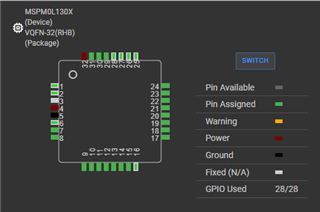
I want to read the PA23 pin of the L1305.

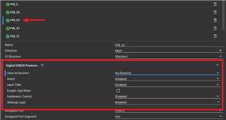
The circuit has a 1.8V pull-up.

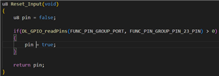
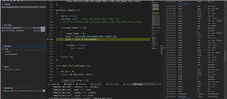
I'm using DL_GPIO_readPins() to read it.

However, for some reason, this pin seems to be floating.and the if condition never evaluates to true.

When reading the register, it sometimes shows high, sometimes low, and even stays low continuously.
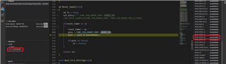
In debug mode, I have to pause and resume several times before the register reads the correct value.
I can confirm that the 1.8V is stable.

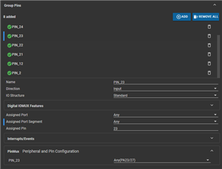
Below are the function and sysconfig settings


Is there anything that needs to be modified?

  • Hey Keng,

    Is this on a TI EVM or a custom board?  You measured the voltage on the pin and confirmed it's a solid 1.8v?  

    What is the VDD of the MSPM0?  Is it also 1.8V?  

    Can you double check the "digital IOMux features" drop down there and confirm there isn't an internal pull-down resistor or something.  

    Finally, is it only PA23?  Is it working on those other GPIO you have defined?  

    Thanks,

    JD

  • The board I designed is a 1.8V system, so the VDD of the L1305 is also 1.8V.

    Additionally, I noticed a strange issue: when I connect the SWDIO or SWCLK of the XDS110, the VDD voltage becomes 2.4V.

    I measured the SWDIO voltage and found it to be 3.3V. Could this be causing voltage backfeeding? Should SWDIO and SWCLK also be level-shifted to 1.8V?

    I'm also not sure if this is the cause, but debugging mode often encounters errors. I have a C1104 EVM Board, and it’s much more stable when using debug

    mode.


  • I encountered a very frustrating issue while coding.

    As shown in the image, Breakpoint stops at line 154, I need to read the status of PA23, so I’m reading the value of the relevant register.

    In debug mode, I can see that the value of the DIN23_20 register is 0x01010000. However, when I directly read the register, the value of pins is 0x00000000.

    Could you explain why this is happening?

    As for why I'm not reading DIN31_0, it’s because I found that DIN31_0 occasionally doesn’t update its value, even though DIN23_20 has already been updated.

    4o
  • Hello Keng, 

    For your debugging, can you check the disassembly view?  It's possible that the compiler has merged these two lines in a way that when you get to this step, the bit mask has actually already been applied.  

    As for programming, it should also be 1.8V.  As you have it setup, it does seem you are back powering the device somehow which will reduce the debug/programming reliability and could damage the device.   What programmer are you using?  If you go into the .ccxml file, you may be able to manually select a lower voltage.  Some programmers also have a pin that allows you to apply the board VDD and it will level shift to that.

    Finally, which package are you using on your custom board?  

    Thanks,

    JD


  • Programmer : XDS110

    I’m not very familiar with assembly language. Could you help me check if there’s any issue?