This thread has been locked.

If you have a related question, please click the "Ask a related question" button in the top right corner. The newly created question will be automatically linked to this question.

MSPM0L1306-Q1: MSPM0G350x / MSPM0L130x Safety Manual Interpretation on external Safety Mechanisms

Part Number: MSPM0L1306-Q1

Tool/software:

Reference's:
MSPM0G Safety Manual SFFS624 03/2024
MSPM0L Safety Manual SFFS619 12/2023


Topic 1: SYSCTL10 External voltage monitor
(Use an external voltage monitor on VCORE pin to monitor the LDO output)

Question 1.1 Fault Detection Failure Modes:
Which Failure Modes need to be monitored (OV-Overvoltage, UV-undervoltage, other-please specify if necessary) ?
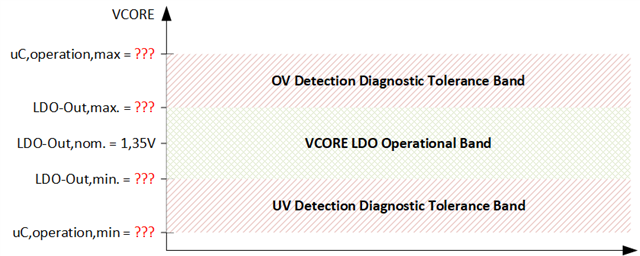
Question 1.2 OV/UV Failure Mode - Fault Detection Bands:
The Data Sheets only specifies the nominal VCORE output voltage by 1.35V. The DS do not specify
- The VORE output Band (min/max voltage output of VCORE)
- The microcontroller operational bands for VCORE.
-> Actually these parameters are necessary, in order to to design UV / OV fault detections
? What is the min/max VCORE LDO output ?
? What is Microcontrollers the min/max operational range of VCORE ?

Question 1.3 OV Failure Mode - Expected Fault Reaction:
What is the expected Fault Reaction, in case the VCORE-OV fault detection trips?
(e.g. VDD shutoff , NRST holding low, other)

Question 1.4 UV Failure Mode - Expected Fault Reaction:
What is the expected Fault Reaction, in case the VCORE-UV fault detection trips?
(e.g. VDD shutoff , NRST holding low, other)


Topic 2: SYSCTL15 External voltage monitor
MSPM0G-SFFS624 (An external voltage supervisor can be used to monitor the power supplies)
MSPM0L-SFFS619 (An external voltage supervisor can be added to the system, which can monitor the VDD line and pull the reset if the VDD is out of expected range.)

Question 2.1 Fault Detection Failure Modes:
Which Failure Modes need to be monitored (OV-Overvoltage, UV-undervoltage, other-please specify if necessary) ?

Question 2.2 UV Failure Mode Coverage by BOR:
Is UV fault detection and reaction already sufficiently covered by BOR (SYSCTL14)?

Question 2.3 UV Failure Mode Coverage by BOR:
What is the expected Fault Reaction, in case the VDD-OV fault detection trips?
(e.g. VDD shutoff , NRST holding low, other)
(within MSPM0L-SFFS619 NRST pulling low is specified. Is the NRST pulling low avoiding silicon pre-damage in case of OV?)


Topic 3: other external Safety Mechanisms required by MSPM0 for ASIL B operational use case
I could not identify other SM requirements on external Safety Mechanisms, that need to be designed by the System Integrator.

Question 3.1
Are other Safety Mechanisms to be externally designed by the System Integrator?

  • Add expert here for more comments

  • Hi Stephan,

    Sorry for late response.

    Please see my updates below.

    Question 1.1 Fault Detection Failure Modes:
    Which Failure Modes need to be monitored (OV-Overvoltage, UV-undervoltage, other-please specify if necessary) ?

    Both. The Vcore output should in the range of the typical value, too larger or smaller both represent the MCU is in fault status。

    ? What is Microcontrollers the min/max operational range of VCORE ?

    Sorry, I also do not know this, let me double check.

    Question 1.3 OV Failure Mode - Expected Fault Reaction:

    This means internal volate is too high, and will make the damage to internal circuit.

    Question 1.4 UV Failure Mode - Expected Fault Reaction:

    Not specific one. It means the internal voltage is abnormal, so CPU might run out of control, also with peripheral.

    Sometimes, if the Vcore not connected to 0.47uf capacitor, user will find sometimes the MCU is out of control due to Vocre drop.

    Question 2.1 Fault Detection Failure Modes:

    At least OV for this.

    Question 2.2 UV Failure Mode Coverage by BOR:

    From my point of view, yes. Unless the BOR circuit is failed.

    What is the expected Fault Reaction, in case the VDD-OV fault detection trips?

    When VDD off, the MCU will not work. All power lost.

    When NRST keeps low. The MCU will not work, while the internal power is keeping, and internal LDO works normal.

    When Over voltage occurs in VDD or other GPIO, NRST could not protect it from damage. The damage is for the internal circuit.

    Are other Safety Mechanisms to be externally designed by the System Integrator?

    Yes, correct. This requires your functional safety team to do evaluation and integrate.

    By the way, MSPM0L1306-Q is not a ASIL-B device, it is TI FS-QM device.

    B.R.

    Sal

  • Hi Sal,

    please clarify on MSPM0L130xQ  ASIL B capability.

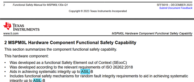
    within Safety Manual SFFS619 - chapter 2 it is clearly defined as ASIL B device.

    You now state it is not. So either YOU or the Safety Manual is wrong. --> How does this go together ?

     it 

    Thank you for answer's:

    Question's 1.1 , 2.1 --> this answer's helps

    For the other answer's, you left open the content or sneaked out of the question. Therefore, please again, reply to the content.

    Question 3.1 other external safety mechanisms:

    you referred to functional safety team. But actually the Safety Manual states the MSPM0L130x / MSPM0G350x to be SAFETY ELEMENTS OUT OF CONTEXT. Therefore, external assumptions on safety mechanism are generic AND HAVE To be specified within the safety manual or supporting documentation (please refer to ISO26262-10:2018, if you do not believe).

    --> Please answer the question 3.1!  

    --> It is really an appropriate yes (then what) or no question. Pregant or not-pregnant ... there is nothing in  between Slight smile.

    Question 1.2 - VCORE UV/OV fault detection bands.

    What are the bands for the UV/OV in terms of voltage?

    This is generic depending on the silicon. TI must specifiy, otherwise the integrator is not capable to use the device for safety relevant applications.

    Question 2.2 - You did not answer my question.

    Interpretation: In case BOR circuit fails, we would have a latent dual-point fault, as it is a pure safety mechanism (assumption TBC) without nominal functionality. As for ASIL B no LFM requirement is present, the BOR is sufficient for monitoring VDD UV.

    --> Is this interpretation correct ?

    Question 1.3 / 1.4 --> What are VCORE UV / OV expected fault reactions ?

    (you did'nt answer. You just told, what is obvious.)

    More specific:

    --> Is for  VCORE OV  a VDD shut-off an appropriate fault reaction ?

    --> Is for VCORE UV s NRST pull-low an appropriate fault reaction ?

    Question 2.3 What is VDD-OV expected fault reaction?

    (you did'nt answer. You just told, what is obvious.)

    Interpretation: NRST cannot be used, as DS specs are violated , contradicting safety relevant usage assumptions.

    Therefore only VDD shut-off can be used.

    --> Is this interpretation correct ?

    sorry for being very punctuated. But actually think about the questions like this...

    If TI is not capable to specify system integrator constraints for safety relevant usage to a level, that allows HW design on integrator site, the causal conclusion would be quite big:

    - The Safety Case for all MSPM0 L130x/G350x devices is not valid

    - TI would have a product safety issue

    - TI would have to spot an early problem notification on every customer

    - TI would have to spot a product recall for every company, that started a design with Safety relevant usage

    regards.

    Stephan

  • Hi Stephan,

    First of all, I need clarify the FS-QM and ASIL-B statement for MSPM0L1306-Q1:

    This clarify the system level ASIL-B implementation, while the device is not a ASIL-B compliant.

    As I know, using FS-QM device with for example other ASIL-B device could also meet the system level ASIL-B requirement.

    We are aware of this could make the customer confused and lead them to incorrect way, and I have reported to the functional safety team. We will update the document ASAP in next few weeks. The documents released last year, and the contents need correction. Sorry for this.

    I will recommend MSPM0L122x-Q device, which will be the first ASIL-B device and could cover the MSPM0L1306-Q.

    The others question I will double check and reply here.

    B.R.

    Sal

  • Hi Stephan,

    I summary your pending question on functional safety below:

    1.Are other Safety Mechanisms to be externally designed by the System Integrator?
    ->  It is really an appropriate yes (then what) or no question.

    Answer:[Updated]

    We only have one system assumption, the external system needs to monitor the VDD. No other assumption has been made.

    2.VCORE UV/OV fault detection (SYSCTL10)

    2-a. What are the bands for the UV/OV in terms of voltage?

    Answer: [Updated]

    I need discuss internally how to release this data within our datasheet or somewhere else. If you requires this data urgent, please contact TI sales team for further support, we can update in email.

    2-b. What are VCORE UV / OV expected fault reactions?

    Answer: [Updated]

    We do not guarantee the correct functioning, which is why VCORE has to be monitored and the action has to be taken at the system level.

    --> Is for  VCORE OV  a VDD shut-off an appropriate fault reaction ?

    Yes.

    --> Is for VCORE UV s NRST pull-low an appropriate fault reaction ?

    TBD. (I tend to shut-off the VDD.)

    [Updated]: It depends on the safe state of the system. If we pull NRST low or shut off the VDD, in both cases, the pins will not drive any value. If this is inline with the system safe state either method should be OK.

    3. VDD UV/OV fault detection (SYSCTL15)

    3-a. Is UV fault detection and reaction already sufficiently covered by BOR (SYSCTL14)?

    [Updated]: BOR only monitors the VDD rail and not VCORE rail. It covers UV, but not OV.

    3-b. What is VDD-OV expected fault reaction?

    Therefore only VDD shut-off can be used.

    Answer: Yes.

    I tried with partial comments here, and will forward the thread to the functional safety team to get feedback. [Update the feedback inline]

    Please let me know if I missed.

    B.R.

    Sal

  • Hi Stephan,

    Update the comments inline with the last reply.

    B.R.

    Sal

  • Hi Sal,

    Thank You so far. The answer's so far are quite good. Some critical points are still missing (e.g. VCORE UV/OV fault detection bands, other ext. SMs necessary.).

    One thought on VORE_UV Monitoing Fault Reaction:

    -> doing VDD Shutoff, may result in a causal loop (VCORE cannot ramp-up without VDD. Therefore VCORE_UV will permit cutoff VDD and UV is tripping all the time). Therefore, NRST_low seems to be the only reasonable fault reaction. The question is: is it appropriate from Silicon Level Analysis?

    B.R.

    Stephan 

  • Hi Stephan,

    VCORE UV/OV fault detection bands,

    This I need to check how to exposure, please send a email to me and then I can see how to update this.

    other ext. SMs necessary

    Except the external voltage monitor, there is no others defined by TI.

    The question is: is it appropriate from Silicon Level Analysis

    Yes, keep NRST low is a vaild operation.

    B.R.

    Sal