This thread has been locked.

If you have a related question, please click the "Ask a related question" button in the top right corner. The newly created question will be automatically linked to this question.

MSPM0C1104: BLDC motor position

Part Number: MSPM0C1104
Other Parts Discussed in Thread: SYSCONFIG

Tool/software:

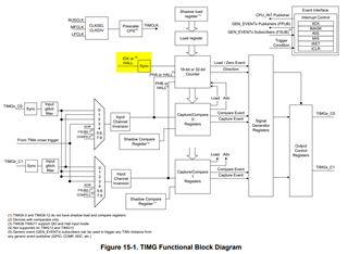
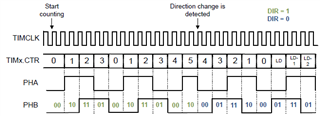
I would like the 3 hall inputs from the BLDC motor to MSPM0 to count the motor position using the hardware in the QEI.

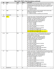
chapter 15.2.3.1.3 QEI Mode does not seem to provide sufficient answer.

I have read "timg_qei_mode" example from SDK, but it only has two inputs, and does not show how to read the position.

  • Hello Jan, 

    Are you asking specifically about the 3rd, IDX pin connection?  

    I haven't used it before, but I see it listed in the IO pin mux for most of the packages.  The pin would need to be configured accordingly.  

    As for having this bit affect the timer, you can see it fed in the block diagram here:

    And for the IDX to have the Timer count reset to zero, I believe you just need to set the CZC bits correctly.  

    Thanks,

    JD

  • hi JD,

    thanks for fast answer.

    So now I can connect my hall sensors to the uC.

    I assume the position counting can be done by the QEI hardware, but if not, I suppose I need to generate interrupt and do the counting in software.

    This picture shows the position counting I want to achieve.

    clockwise counter clockwise
    hall A 1 1 1 0 0 0 0 0 1 1 1 0
    hall B 0 0 1 1 1 0 1 1 1 0 0 0
    hall C 1 0 0 0 1 1 1 0 0 0 1 1
    position 1 2 3 4 5 6 5 4 3 2 1 0

    This is shown below for two hall signals, and the same is true for 3 hall signals. I expect that the MSP can do this counting in hardware, but where do I read the counter value?

    From data sheet chapter 15.2.3.1

    I have tried to configure this in the sysconfig tool, but I don’t know if this creates the counting that I want and where to read the counting result.

  • Hey Jan,

    The Timer's count value is stored and the timer counter register TIMx.CTR. I don't have personal experience with a 3 hall sensor application and it's also unclear to me if the timer will be able to keep a count as you proposed.  I do see that you can clearly XOR the 3 hall signal internally to get a pulse wave for measuring speed.  

    I did find our Hall Sensored Trap Motor Control example, which is a motor drive example in our MSPM0 SDK that uses 3 hall sensors.  Scanning the example, it seemed like maybe they were using GPIO interrupts to set the states you listed and the timer to measure speed.  I will let you take a look.  

    The TIMx module is probably the most complicated peripheral and this is a more complex use case.  Let me see if I can find someone on the team tomorrow who may have some experience configuring this type of application. 

    Thanks,

    JD