This thread has been locked.

If you have a related question, please click the "Ask a related question" button in the top right corner. The newly created question will be automatically linked to this question.

LP-MSPM0G3507: LP-MSPM0G3507

Part Number: LP-MSPM0G3507
Other Parts Discussed in Thread: UNIFLASH, SYSCONFIG, MSPM0G3107

Tool/software:

Hi,

I am using the G3107 which is custom PCB with XDS110 debugger, Initially I am able to flash and debug it.

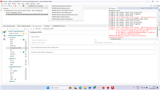
After couples of times of flashing I am not able to flash it. I tried various settings in CCS and even Uniflash and I always getting the same error -615 and sometimes 

This is the complete log I get when pressing "Test connection":

[Start: Texas Instruments XDS110 USB Debug Probe]

Execute the command:

%ccs_base%/common/uscif/dbgjtag -f %boarddatafile% -rv -o -S integrity

[Result]


-----[Print the board config pathname(s)]------------------------------------

C:\Users\2072742\AppData\Local\TEXASI~1\
CCS\ccs1271\0\0\BrdDat\testBoard.dat

-----[Print the reset-command software log-file]-----------------------------

This utility has selected a 100/110/510 class product.
This utility will load the adapter 'jioxds110.dll'.
The library build date was 'Apr 19 2024'.
The library build time was '14:04:01'.
The library package version is '12.7.0.00130'.
The library component version is '35.35.0.0'.
The controller does not use a programmable FPGA.
The controller has a version number of '5' (0x00000005).
The controller has an insertion length of '0' (0x00000000).
This utility will attempt to reset the controller to enter SWD mode.

-----[Print the reset-command hardware log-file]-----------------------------

This emulator does not create a reset log-file.

-----[Perform the SWD Mode Integrity test]-----------------------------------

This test will read the IDCODE register 1 time.


-----[An error has occurred and this utility has aborted]--------------------

This error is generated by TI's USCIF driver or utilities.

The value is '-615' (0xfffffd99).
The title is 'SC_ERR_SWD_PROTOCOL'.

The explanation is:
The target failed to see a correctly formatted SWD header. The
connection to the target may be unreliable. Try lowering the
TCLK setting before trying again.

[End: Texas Instruments XDS110 USB Debug Probe]

and another error is like below

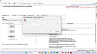
Please Provide the solution to resolve this asap. Thanks!

  • Hi Sravan, 

    What code have you flashed to the device? Is it possible that you disabled the SWD interface, or changed it in some way? This is configured in the device's NONMAIN region. If you are configuring the device with Sysconfig it should be pretty easily clear whether this has been changed, as you would have had to change the "Configuration NVM" tab in the Sysconfig GUI.

    This error code indicates that the debugger is not able to detect a proper SWD header, meaning that SWD communication between the debugger and the MSPM0G3107 is not working correctly. 

    This could also happen if the connection between the MSPM0G3107 and the debugger is incorrect. Can you double check your schematic, and the actual hardware, to ensure the connections are correct?

    You could also try resetting the device, putting it into BSL mode, or if possible try to factory reset the device. 

  • Initially I flashed I2C code which I was configured (sysconfig not used) then I got this error. From there onwards I am trying to flash G3107 Empty project only.

    Additional information, 

    I am using XDS110 debugger of G3507 Launchpad to connect my target. I removed all the jumper pins(J101) of XDS debugger, and I connected debugger pins of GND, NRST, SWDIO, SWCLK to G3107 PCB. I am able to flash the same code using the same connections in other chip.  

    Now I not able to execute the script commands as shown in the below image


    Could you please let us know how we can recover the PCB's after this error got triggered? And what are the reasons for this error?
    Would appreciate your quick support.

  • So if your I2C code changed the configuration of the SWD pins, meaning that the PINCM values of those pins were changed, this error makes sense to me. What you would need to do to recover the device would be to start by placing the device in BSL mode by holding PA18 high while you power the device on or reset it. Once this is done, the configuration of the SWD pins will be returned to the original state configured by your NONMAIN region. The device will remain in BSL mode for 10 seconds before going to sleep. So quickly after putting into BSL mode, issue a factory reset to the device using the scripts shown in your screenshot. This will erase the application code that incorrectly configures the SWD pins' PINCM values, which would allow you to access the device as normal again.

  • Thanks Dylan OBrien, we tried pulling up PA18 and tried factory reset and it helped to recover the board.