


Part Number: MSP432E401Y
Other Parts Discussed in Thread: TPS2052B
Tool/software:
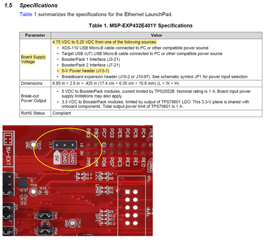
which pins/connector do I connect an external DC power supply to power up this circuit board
Part Number: MSP432E401Y
Other Parts Discussed in Thread: TPS2052B
Tool/software:
which pins/connector do I connect an external DC power supply to power up this circuit board

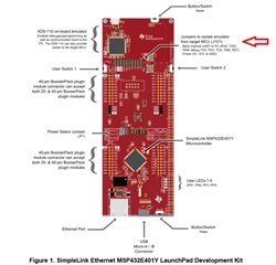


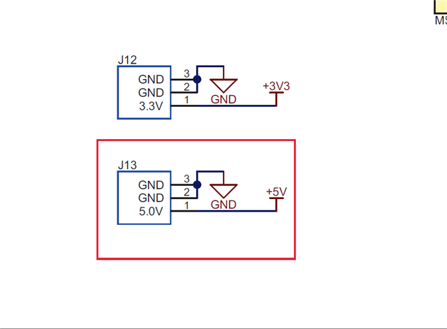 Do I still need to make jumper changes to JP1? and J101? Thanks again for everyone's time and help.