Part Number: MCU-PLUS-SDK-AM243X
Other Parts Discussed in Thread: BP-AM2BLDCSERVO
Tool/software:
Hi there,
We are evaluating hardware LP-AM243x and BLDC BP (i.e. BP-AM2BLDCSERVO). We are using two own in-house motors and two eQep for two incremental encoders, and sdfm with 6 channels to measure the currents. We are basically using motor_control_sdk 9.2.0.09 example project single_chip_servo.
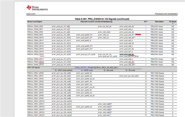
I need some clarification about pin multiplexing. The syscfg for R5FSS0-0 in single_chip_servo project is consistent with Table 2-2. SDFM Signals in TIDUF42 -January 2024 pp.5. However, how can PRG0_PRU0_GPI7, -GPI8, and GPI11 function as data lines for SD3_D, SD6_D and SD7_D (see SPRUJ87 - June 2023. pp.22 Figure 2-23). Or how could the very three pins represent any other SDx_D lines by chance, which deviates from Figure 2-23 but might still work. However, PRG0_PRU0_GPI7 PRG0_PRU0_GPO8 is SD4_CLK and could not function as any SDx_D (see TRM spruim2h - May 2020 -Revised October 2023. pp3305 Table 6-417).
I would prefer to set up a call with you. I am located in Germany.
Best regards,
Jinlong