


Part Number: LP-AM243
Tool/software:
Both the E3 schematic pin listing (page7) and the evaluation guide (page29) give the wrong pins for TEST_LED3 and TEST_LED4. They claim the LEDs are connected to PRG1.

They're actually connected to PRG0. Snippet from E3 schematic confirms:
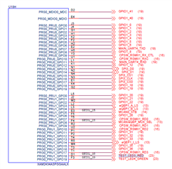
I have confirmed LED3 and LED4 are connected to PRG0_PRU1_GPO18/D1 & PRG0_PRU1_GPO19/F3 by writing an example app.
Using the wrong pins prevents the Ethernet from working.
