Tool/software:
Hi,Dear TI Engineer friends!
Here's a description of the problem I ran into:
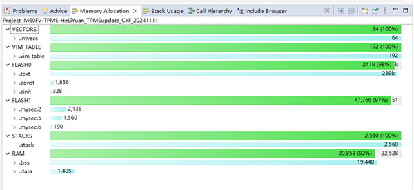
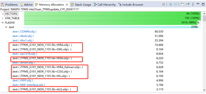
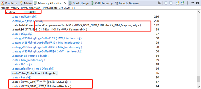
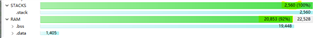
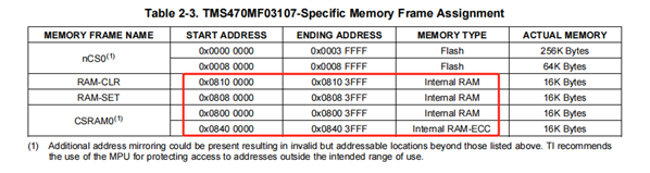
Our system program is developed based on TMS470MF03107. After integration of this system program, the total RAM space required by RAM is 0x5178 bytes. The actual chip memory resources are shown in the following figure:
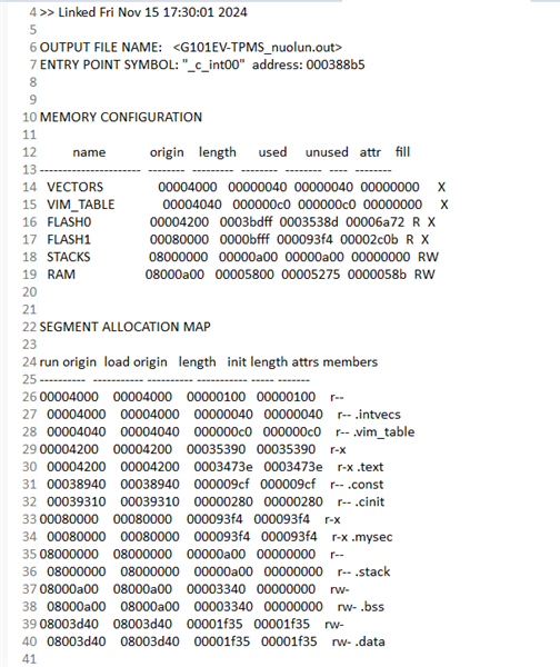
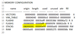
The current sys_link.cmd file is as follows:
/*----------------------------------------------------------------------------*/
/* sys_link.cmd */
/* */
/* (c) Texas Instruments 2011, All rights reserved. */
/* */
/* USER CODE BEGIN (0) */
/* USER CODE END */
/*----------------------------------------------------------------------------*/
/* Linker Settings */
-l rtsv7M3_T_be_eabi.lib
--retain="*(.intvecs)"
--retain="*(.vim_table)"
/* USER CODE END */
/*----------------------------------------------------------------------------*/
/* Memory Map */
MEMORY
{
VECTORS (X) : origin=0x00004000 length=0x00000040
VIM_TABLE (X): origin=0x00004040 length=0x000000C0
//FLASH0 (RX) : origin=0x00004100 length=0x0003BF00 //20130516
FLASH0 (RX) : origin=0x00004200 length=0x0003BDFF //0x0003BE00//20140318
//FLASH1 (RX) : origin=0x00080000 length=0x00007FFF
FLASH1 (RX) : origin=0x00080000 length=0x0000BFFF //length=0x00007FFF
STACKS (RW) : origin=0x08000000 length=0x00000A00 //800
RAM (RW) : origin=0x08000A00 length=0x00005800// length=0x00003600//length=0x00005800 //800--5800//20200409
/* USER CODE BEGIN (1) */
/* USER CODE END */
}
/* USER CODE BEGIN (2) */
/* USER CODE END */
/*----------------------------------------------------------------------------*/
/* Section Configuration */
//-----------------------KWP.obj (.text)// EBD.obj (.text)---// ------------
SECTIONS
{
.intvecs : {} > VECTORS
.vim_table : {} > VIM_TABLE
.mysec : {
EBD.obj (.text)
CAN.obj(.text)
//dirver.obj (.text)
PI.obj (.text)
GT.obj (.text)
SCI.obj (.text)
//KWP.obj (.text)
gio.obj (.text)
spi.obj (.text)
VSO.obj (.text)
M301CAN.obj (.text)
diag.obj (.text)
alldriver.obj (.text)
} >FLASH1
.text : {} > FLASH0
.const : {} > FLASH0 | FLASH1
.cinit : {} > FLASH0 | FLASH1
.pinit : {} > FLASH0 | FLASH1
.bss : {} > RAM
.data : {} > RAM
.sysmem : {} > RAM
.stack :
{
. += 0x00000500; _Stack_Table_Pointer = .; //400//20200409
. += 0x00000500; _Stack_Handler_Pointer = .; //400//20200409
} > STACKS
}
/* USER CODE BEGIN (3) */
/* USER CODE END */
//}
/* USER CODE BEGIN (4) */
/* USER CODE END */
/*----------------------------------------------------------------------------*/
/* Misc */
/* USER CODE BEGIN (5) */
/* USER CODE END */
/*----------------------------------------------------------------------------*/
Questions are as follows:
1) You can see that the length of RAM 0x5800 has exceeded the single RAM length 0x3FFF in the current code Settings, is it reasonable? If not, how do you configure it in memory?
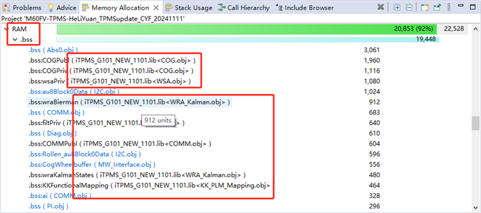
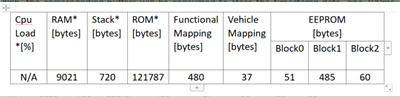
2) The system program is divided into two parts, one occupies 9000 bytes of RAM (0x2328), and the other occupies 11856 bytes (0x2E50). Considering that the program needs to generate a part of RAM occupation for dynamic data processing, combined with the above chip's own RAM resources, how to solve the problem of static memory allocation? And how to keep the dynamic running program stable? The following is the resource occupation situation of dynamic operation of part of the system program, please refer to it: When the vehicle speed data input is more than 100kph, the corresponding buffers will be consumed to store the timestamp data, one 100ms buffer and three 20ms buffers, a total of 992 bytes;
3) Having triedusing RAM memory segment 0x08080000-0x08083FFF to expand RAM storage space, the main code segment is as follows:
...
RAM0 (RW) : origin=0x08000A00 length=0x00003600//length=0x00005800 //800--5800//20200409
RAM1 (RW) : origin=0x08080000 length=0x00003FFF
...
.bss : {
*(.bss*)
*(.bss_ram1)
. = ALIGN(4);
} > RAM0 | RAM1
.data : {
*(.data*)
*(.data_ram1)
. = ALIGN(4);
} > RAM0 | RAM1
.sysmem : {
*(.sysmem*)
. = ALIGN(4);
} > RAM0 | RAM1
.bss : {
*(.bss*)
iTPMS_G101_NEW_1101.lib (.bss)
. = ALIGN(4);
} > RAM1
.data : {
*(.data*)
iTPMS_G101_NEW_1101.lib (.data)
. = ALIGN(4);
} > RAM1
.sysmem : {
*(.sysmem*)
iTPMS_G101_NEW_1101.lib (.sysmem)
. = ALIGN(4);
} > RAM1
...
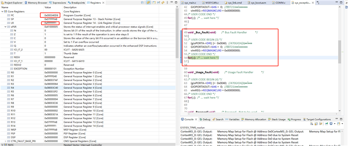
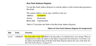
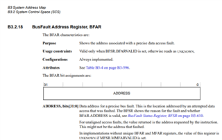
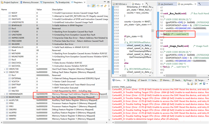
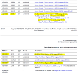
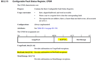
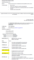
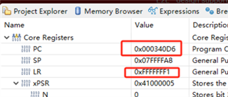
It compiles without an error, but the program runs incorrectly (some part of the system doesn't work). Then I saw this detail in the chip manual:
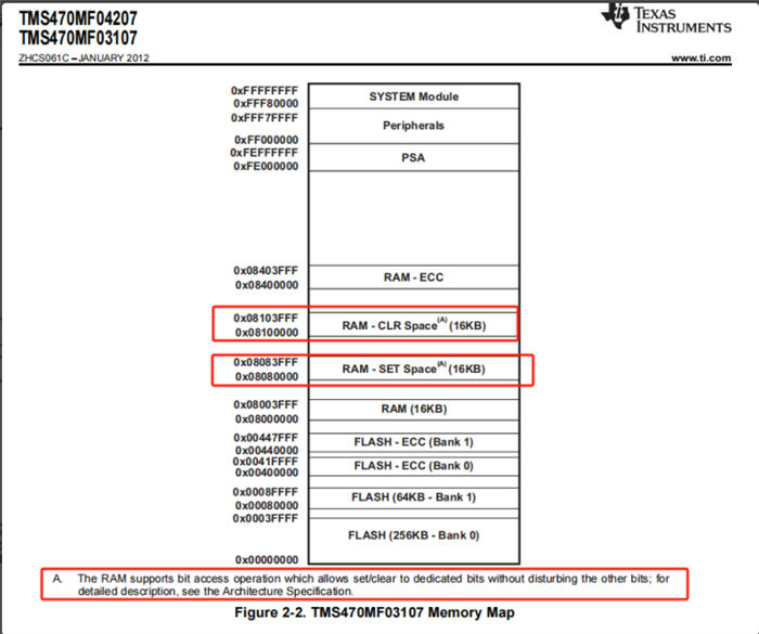
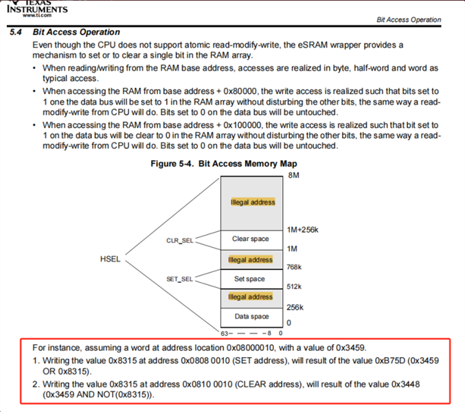
4) Does this mean that the RAM-CLR Space and RAM-SET Space cannot be used as regular random storage areas for programme running? What is the purpose of the two regions RAM-CLR Space and RAM-SET Space? Based on the resource requirements of this system program, how to apply TMS470MF03107 this chip's RAM distribution?
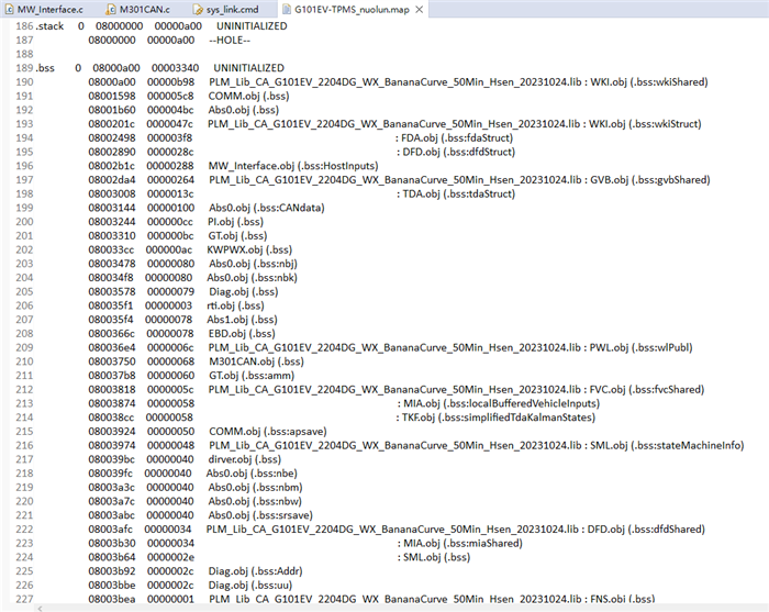
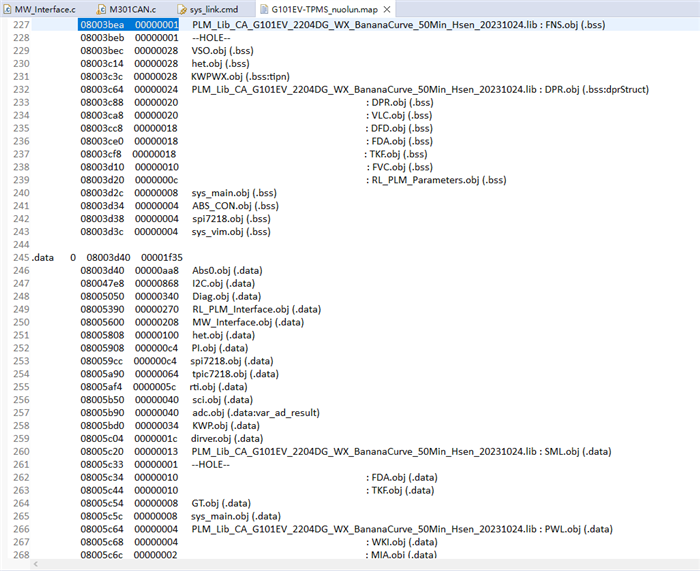
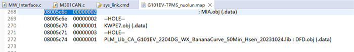
5) At present, the static occupied RAM space after compilation is 0x5180, and the configuration size of linkCMD file is 0x5800, which have exceeded the size of 0x3FFF specified in the chip manual. Why are there still CAN message? Shouldn't it be theoretically out of memory? How to intuitively determine whether the program is overflowing? I've already used sentinel values, but they don't work well.
Because it is urgent, I hope to get an accurate answer from you or relevant personnel of your company, thank you!