AM2432: Pulse Train Output Control and Synchronization

Part Number: AM2432
Other Parts Discussed in Thread: SYSCONFIG,

Tool/software:

Hi TI Experts,

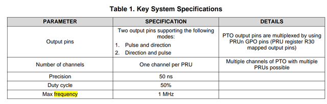
In AM335x, we have a below application note that describes how to perform high performance pulse train output (PTO) with PRU-ICSS.

High Performance Pulse Train Output (PTO) With PRU-ICSS for Industrial Applications.pdf

And it could achieve maximum 1MHz outputting pulse + direction. 

Customer wants to the similar design on AM243, may I know if it is feasible or not, since we also have PRU in AM243?

The only difference is that customer outputs pulse + pulse not pulse + direction.

Customer is also wondering if they could achieve higher frequency greater that what we achieved 1MHz in AM335x?

Many Thanks,

Kevin

  • Hello Kevin

    Thank you for the query.

    I may have to check internally.

    Please expect delay in response due to the holiday week.

    Regards,

    Sreenivasa

  • Hi Kallikuppa,

    We are trying to simulate A/B pulse output with this design. The current product is able to output at 5 Mhz.

    Thanks,

    Jianyu

  • Hello Jianyu

    Thank you.

    Can you add some additional details.

    Regards,

    Sreenivasa

  • Hi Kallikuppa,

    The design is called Encoder Emulate Output(EEO), which is to emulate A/B signal when drive is using serial encoder like Biss-c, Tamagawa, etc.

    The customer can manually set the number of pulse per revolution.

    So we have PRU-A for EEO and PRU-B for Position feedback(Biss-c, Tamagawa,...). Both of them is synchronized with EPWM module.

    PRU-B will trigger interrupt every 62.5 us after new feedback is arrived.

    Once this interrupt is triggered,  R5F would calculate the position difference with direction. R5F will write 2 parameters(number of pulse and direction) to PRU-A.

    PRU-A would output that number of pulse at set direction when next interrupt of EPWM arrived.

    Thanks,

    Jianyu

  • Hello Jianyu

    Thank you.

    Regards,

    Sreenivasa

  • Hi TI Experts,

    Thanks for your plan to support this case, please see the 3 requirements from customer below.

    1: Max Frequency: 5MHz

    2: PWM Duty Ratio: 40% ~ 60%

    3: A, B Phase Difference: 70 degree ~ 110 degree

    Thanks,

    Kevin

  • Hi Kallikuppa,

    There is some more info we want to add,

    1. PRG1_PRU0 is both used for Biss-c / Tamagawa encoder and EEO output

    2. GPO13 for encoder Rx, GPO0 for encoder clk, GPO1 for encoder TX

    3. GPO17 for EEO-A, GPO18 for EEO-B and GPO19 for EEO-Z

    4. We are thinking RTU_PRU0 for EEO and PRU0 for encoder so they can both use IEP0.

    Is this setting feasible?

    One extra function I would like add for EEO, is EEO-Z for index signal.

    R5F core would write 3 parameters,

    1. Enable register, means there is an index at next cycle.

    2. Delay count, means after delay count of pulses, GPO19 is set.

    3. Manual high,

         - 0: Index is set for 1/4 pulse width of A and B.

         - 1: Index is set until this param is reset. This setting is used for controllers that require the signal to stay set for certain X ms.

    Thanks

    Jianyu

  • PRG1_PRU0 is both used for Biss-c / Tamagawa encoder and EEO output

    Unfortunately, this is not possible to do any sort of GPO output when 3-channel peripheral interface mode is configured for PRG1_PRU0.


    So, in this use case, you can switch between BISS-C/Tamagawa to EEO output (i.e. no need to run them simultaneously)?

    For simultaneous use, only potential alternative is to use PRU_ICSSG PWM Module for pulse generation (assuming IEP0 usage is consistent), so you will need to pick couple of PRG1_PWMx_A/Bx and one of PRG1_PWMx_TZ_OUT or PRG1_IEP0_EDIO_DATA_IN_OUT[31:28] for Index signal.

  • I checked with pinout, so we are using AM2431-ALV. 

    IEP0 is currently configured as 200Mhz. Encoder and EEO would be used simultaneously.

    So AA9 and Y9, orignally PRG1_PRU0_GPO14 and PRG1_PRU0_GPO15, when configured as PRG1_PWM0_A1 and PRG1_PWM0_B1, can be used as EEO A/B output? 

    And W7 when configured as PRG1_PWM0_TZ_OUT, can be used as EEO index?

    Thanks,

    Jianyu

  • Hi Jianyu Wang and Kevin Peng,

    1: Max Frequency: 5MHz

    2: PWM Duty Ratio: 40% ~ 60%

    3: A, B Phase Difference: 70 degree ~ 110 degree


    1) who is configuring Frequency, Duty cycle, Phase Difference at run time?

    One extra function I would like add for EEO, is EEO-Z for index signal.

    R5F core would write 3 parameters,

    1. Enable register, means there is an index at next cycle.

    2. Delay count, means after delay count of pulses, GPO19 is set.

    3. Manual high,

         - 0: Index is set for 1/4 pulse width of A and B.

         - 1: Index is set until this param is reset. This setting is used for controllers that require the signal to stay set for certain X ms.

    2) Can you give us few example wave forms generating index, PWM A, PWM B signals?


    Thanks and regards,
    Manoj.

  • who is configuring Frequency, Duty cycle, Phase Difference at run time?

    The PRU module do. The R5F core would write the number of pulse and direction to PRU after each cycle. PRU should calculate the relevent value to PWM module.

    The frequency is the number of pulse. duty cycle fixed to 50%. Phase difference is fixed to 25%.

    Here is screenshots of EEO output from our current product. The pulses per revolution is 80000. Yellow, green, orange is A, B, Z respectively.

    1. Index signal when V = 60 rpm. MCU writes 5 pulses in every cycle. Each pulse width should be 6.25 us, and index pulse width should be 3.125 us.

    Also, A/B starts alternately in each cycle due to the odd number in each cycle.

    2. Index signal when V = 600 rpm. The pulse width for A, B, Z should be 10 times smaller compared to V = 60 rpm. 

    3. When manualled index mode is on, PRU would still set phase Z after the set number of pulses. The index is reset when core reset the register.

  • Thanks for the details, we are discussing and scheduling the timeline internally.

  • Hi Manoj,

    Here is an update on pin selection. We want to use V21 PRG1_PWM2_A2, R16 as PRG2_PWM2_B2, and U12 PRG1_PWM2_TZ_OUT for EEO A, B and Z. 

    Thanks,

    Jianyu

  • Hi Jianyu,

    It is possible to control PRG1_PWM2_TZ_OUT from PRU meeting the conditions you mentioned previously, but all PWM channels corresponding to PWM2 will go to trip state, But I will discuss with the team internally on this whether there are any alternative ways to avoid this.

    Below are the two other options:-

    1)Either we can use PRG1_IEP0_EDIO_DATA_IN_OUT[31:28] or PRG1_PWM1_TZ_OUT, PRG1_PWM3_TZ_OUT, PRG1_PWM4_TZ_OUT as EEO Z.

    Thanks & regards,
    Manoj.

  • Hi Manoj,

    Maybe change to V14 PRG1_IEP0_EDIO_DATA_IN_OUT30?

    BR,

    Jianyu

  • Maybe change to V14 PRG1_IEP0_EDIO_DATA_IN_OUT30?

    sure.

    Thanks & regards,
    Manoj.

  • Hi Manoj,

    Thanks for your strong support, customer has received the example and now is running normally.

    They will do some further testing & evaluations later on, please keep this thread open for a while in case if they meet any additional problems.

    Many Thanks,

    Kevin

  • Hello Kevin,

    Thank you for updating the progress.

    Regards,

    Sreenivasa

  • Re-open this ticket as customer want continues flow up. 

  • Hi Ti experts,

    At the time when we first received the demo, I was only able to compile it due other higher priority tasks.

    I made the following changes in file empty_example.c to make it suit our board,

    1. I2C is removed. I2c_io_expander(null); is commented.

    2. Pinmux_config() is commented. Pin V21, R16 and R20 are added as GPIO output as suggested in the comment.

    3. I notice that line #include <pru0_load_bin.h> would use the header file in the SDK. So I compiled the PRU project and change this line to use the compiled PRU0Firmware_0.

    So when the project is loaded, pin V21 is high. Not sure where went wrong.

    From the code I assuem it should continuously output pulse from given duty cycle based on phase difference.

    Thanks,

    Jianyu 

  • The PRU module do. The R5F core would write the number of pulse and direction to PRU after each cycle

    I noticed that in demo the PWM frequency is 4Mhz. I apology that I didn't indicate that the cycle is PFB cycle, which should be 62.5 us. Would this affect how the demo works?

  • Hi Jianyu,

    Pinmux_config() is commented. Pin V21, R16 and R20 are added as GPIO output as suggested in the comment.
    V21 is mux-ed with PRG1_PWM2_A2 and R16 is mux-ed with PRG1_PWM2_B2 from R5F application itself (Note : there is no pinmux support in sysconfig for PRUICSS PWM signals when this code is shared with you, this is added in latest version of mcu plus sdk, for now let's keep it in R5F project only.)

    we don’t have V14 GPIO signal available to probe on am243x-evm, so we used T20  GPIO Signal, but you can move to V14 GPIO signal from sysconfig GPIO module and updating PRU firmware 172, 173 lines (Initializing  R24 and R25 registers of PRU with gpio base address and data to be written) 270(GPIO set register offset), 273(GPIO clear register offset) lines


    I have done both R5F and PRU firmware changes which I mentioned above(switching to V14 GPIO signal) in this zip file servotronix_v4.zip

    please let us know once the functionality of EEO is evaluated with GPIO signal, we will share again steps to switch V14 to PRG1_IEP0_EDIO_DATA_IN_OUT30 signal.


    1. I2C is removed. I2c_io_expander(null); is commented.

    This is correct.

    I notice that line #include <pru0_load_bin.h> would use the header file in the SDK. So I compiled the PRU project and change this line to use the compiled PRU0Firmware_0.

    This is not requried, once you build PRU project, post build step will move generated pru0_load_bin.h to SDK (move pru0_load_bin.h <mcu_plus_sdk_path>/examples/pru_io/empty/firmware/am243x-evm/pru0_load_bin.h)

    I noticed that in demo the PWM frequency is 4Mhz. I apology that I didn't indicate that the cycle is PFB cycle, which should be 62.5 us. Would this affect how the demo works?

    No this will not effect the demo, PWM frequency is configurable from R5F and the code works up to 4Mhz PWM frequency.

    Thanks & regards,
    Manoj.

  • Great! Now I get the Signal from Pin V21, R16 and R20. I'll change the firmware to match our project design. I'll update the thread if any issue encountered

  • Hi Manoj,

    1. 

    No this will not effect the demo, PWM frequency is configurable from R5F and the code works up to 4Mhz PWM frequency.

    Can you show me how to change it? So we want the EEO output is up to 4Mhz. The data update cycle maybe 62.5 us, 31.25 us, 20us, etc. 

    I changed the initialization function EPWM_tbPwmFreqCfg(epwmBaseAddr, SOC_EPWM_TB_FREQ, SOC_EPWM_OUTPUT_FREQ, EPWM_TB_COUNTER_DIR_UP_DOWN, EPWM_SHADOW_REG_CTRL_ENABLE);

    SOC_EPWM_OUTPUT_FREQ is changed to 16000, but the update frequency seems same, the time between V14 is 1.3us.

    2. It seems update_pru_icss_pwm(SOC_EPWM_OUTPUT_FREQ, 40, 110, 1);, 110 is the PFB difference I should input. How to calculate it? I tested to toggle it between 110 and 55 in App_epwmIntrIrq, the output seems same.

    3. I assume if function update_eeo_parameters() is not called, V14 will output nothing? I see (5, 0) would reset V14 automatically. So if the input is (5, 1), how do I reset the Pin?

  • Hello Jianyu

    #define
    SOC_EPWM_OUTPUT_FREQ                                (16000)

    Above macro is used in configuring IEP_CMP0 value which will determine PRG1_PWM2_A2, PRG1_PWM2_B2 frequency and periodicity of EPWM interrupt to R5F.

    When EPWM interrupt is triggered to R5F, this example updates PRG1_PWM2_A2, PRG1_PWM2_B2, EEO signal 
    parameters in PRUICSS DMEM, EPWM interrupt can be replaced with periodic task as well.


    In  App_epwmIntrIrq, we update PRUICSS PWM parameters in PRUICSS DMEM calling update_pru_icss_pwm

    update_pru_icss_pwm takes pruIcssPwmFreq, dutyCycleOfPwmA_B, phaseDifference(In degree's), phase direction( 1 (+ve direction phase shift) or 0(negative direction phase shift) ) as parameters

    In App_epwmIntrIrq, we update EEO parameters in PRUICSS DMEM calling update_eeo_parameters

    update_eeo_parameters takes delayCount, manualHighFlag as parmeters

    When delayCount is set to 1 and manualHighFlag is 0, EEO frequency will be same as defined in SOC_EPWM_OUTPUT_FREQ (EEO is set and cleared every PWM period)

    when delayCount is set to 2 and manualHighFlag is 0, EEO frequency will be half of the frequency defined in SOC_EPWM_OUTPUT_FREQ 

    When delayCount is set to 0 (index is disabled), there will not be EEO output

    When delayCount is set to 1 and manualHighFlag is 1, EEO will output high after 1 PWM cycle and stays high until manualHighFlag is cleared.

    When delayCount is set to 2 and manualHighFlag is 1, EEO will output high after 2 PWM cycles and stays high until manualHighFlag is cleared.

    So if the input is (5, 1), how do I reset the Pin?
    you can reset or disable EEO output by calling update_eeo_parameters (0, 0) this makes EEO signal low and index is disabled.

    Note :- when delayCount is set 5, firmware will reload delayCount value only after 5 periods(whenever delay count becomes 0) but manual flag status is loaded every PWM period.

    Let me know if you have any questions, I can create and share PRU firmware flow diagram if you need it.

    Thanks & regards,
    Manoj.
  • Let me know if you have any questions, I can create and share PRU firmware flow diagram if you need it.

    That would be appreciated. 

    update_eeo_parameters

    So this function I have noticed that it is aligned to V21 and the pulse length is half pwm cycle. The length when it is high should be 1/4. 

    So for function update_pru_icss_pwm, I assume I should manually set the PWM frequency based on current output. There is one issue, how do I handle the odd pulses?

    Say the update cycle is 16K. Output is 5 pulses, 10, .. till 250 (4MHz). Then the speed is reduced from 250 till 0. Can the demo handle it?

  • Hi Jianyu,

    So this function I have noticed that it is aligned to V21 and the pulse length is half pwm cycle. The length when it is high should be 1/4. 

    Index pulse width is mentioned as 1/4(pulse length of A and pulse length of B) before, if A and B has same duty cycle, then index pulse width is same as duty cycle of A or B right, please let me know if my understanding is wrong here from your requirements or any changes are required?

    So for function update_pru_icss_pwm, I assume I should manually set the PWM frequency based on current output. There is one issue, how do I handle the odd pulses?

    Say the update cycle is 16K. Output is 5 pulses, 10, .. till 250 (4MHz). Then the speed is reduced from 250 till 0. Can the demo handle it?

    If I understand you correctly, update cycle in R5F is 16KHZ and if you want to update PWM frequency as follows (5*16KHZ, 10*16KHZ till 250*16KHZ ) and then speed is reduced from 250*16KHZ to 0*16KHZ, that should be possible and this will require minor modifications in firmware reloading and reconfiguring IEP1 CMP0 which controls PWM frequency (Note : this is not mentioned as requirement earlier).

    Please confirm above, I can make modifications and provide you new version of code.

    Thanks & regards,
    Manoj.

  • If I understand you correctly, update cycle in R5F is 16KHZ and if you want to update PWM frequency as follows (5*16KHZ, 10*16KHZ till 250*16KHZ ) and then speed is reduced from 250*16KHZ to 0*16KHZ, that should be possible and this will require minor modifications in firmware reloading and reconfiguring IEP1 CMP0 which controls PWM frequency (Note : this is not mentioned as requirement earlier).

    Please confirm above, I can make modifications and provide you new version of code.

    Hi Manoj, 

    The purpose of EEO is that we simulate the ABZ output. The number of output pulse should be accurate.

    So we have PRU-A for EEO and PRU-B for Position feedback(Biss-c, Tamagawa,...). Both of them is synchronized with EPWM module.

    PRU-B will trigger interrupt every 62.5 us after new feedback is arrived.

    Once this interrupt is triggered,  R5F would calculate the position difference with direction. R5F will write 2 parameters(number of pulse and direction) to PRU-A.

    PRU-A would output that number of pulse at set direction when next interrupt of EPWM arrived.

    The origin description may be a little vague. You can check https://www.quantumdev.com/understanding-incremental-encoder-signals/

    Index pulse width is mentioned as 1/4(pulse length of A and pulse length of B) before, if A and B has same duty cycle, then index pulse width is same as duty cycle of A or B right,

    In ABZ, each edge, pos or neg of A and B is considered 1 pulse. 

    The index would be set at pos edge of A and reset at neg edge of B if it is in positive direction. And in negative direction, index is set at pos edge of B and neg edge of A.

    To make it more clear is that, I can show a standard scenario.

    1. on power up, the position stable at some point. PRU should set A, B accordingly. It may be (0, 0), (1, 0), (1, 1), (0, 1) based on the input. For this implementation the index would be fixed on the pos edge of A for positive direction.

    2. MCU may output +/- x pulse due to position movement. A and B should be updated to High/low accordingly.

    Say the update cycle is 16K. Output is 5 pulses, 10, .. till 250 (4MHz). Then the speed is reduced from 250 till 0.

    3. The motor starts to rotate in positive direction. It accelerates until the EEO output reaches 4MHz and then decelerates until it is stopped.

  • Hi Jianyu,

    Please find below 
    PRU firmware functional flow diagram:-


    Please find below PRU firmware functional overview :-

    Initialization

    • Disables IEP1 counter and clears PWM2_A2 and PWM2_B2 register configurations
    • Disable compare events
    • Configure PWM2_A2, PWM2_B2 in active state to toggle the signal
    • Enable compare 0, 5, 6, 7 events, CMP0 reset and shadow mode of IEP1
    • Configure CMP0 to (Period/2) 
    • Configure and enable IEP1_CMP7 based task to trigger TM_IEP1_CMP7_TASK 
    • Enable IEP1 with increment value 3
    • Load EEO parameters using lbco and jump to label ( process_iep1_cmp0_intr_0 )

    process_iep1_cmp0_intr_0

    • clear compare events except compare 0 and wait for compare 0 to hit then clear compare0
    • Configure IEP1 CMP5, IEP1 CMP6 to ((period/2) - ((Duty cycle/100)*(period/2)) +/- rise edge delay) which controls rise edge of PRG1_PWM2_A2 and PRG1_PWM2_B2 signals
    • If EEO_SIGNAL_STATE is high, then configure ICSS_IEP_CMP7_REG with CMP_HIGH value so that compare 7 event will not hit and don't trigger task to update state of EEO_SIGNAL else continue below
    • If  eeo_delay_count_value is 0,  then configure ICSS_IEP_CMP7_REG with CMP_HIGH value so that compare 7 event will not hit and don't trigger task to update state of EEO_SIGNAL(this is case is same) else continue below
    • If  eeo_delay_count_value is 1,  then configure  ICSS_IEP_CMP7_REG with pwmACmpUpValue and jump to process_iep1_cmp0_intr_1        

    process_iep1_cmp0_intr_1

    • clear compare events except compare 0 and wait for compare 0 to hit and clear compare 0
    • Configure CMP5 and CMP6 value to ((Duty cycle/100)*(Period/2)+/-(Fall edge delay))
    • If  eeo_delay_count_value is 0,  then configure ICSS_IEP_CMP7_REG with CMP_HIGH value so that compare 7 event will not hit and don't trigger task to update state of EEO_SIGNAL(this is case is same) else continue below
    • subtract eeo_delay_count_value by 1
    • If  eeo_delay_count_value is 0 and eeo_manual_high_flag is 1, then configure ICSS_IEP_CMP7_REG with CMP_HIGH value so that compare 7 event will not hit and don't trigger task to update state of EEO_SIGNAL(this is case is same) then jump to load_eeo_manual_high_status else continue below 
    • if eeo_delay_count_value is 0 and eeo_manual_high_flag is 0, then configure ICSS_IEP_CMP7_REG with CMP_HIGH value so that compare 7 event will not hit and don't trigger task to update state of EEO_SIGNAL(this is case is same) then jump to load_eeo_parameters else continue below
    • configure  ICSS_IEP_CMP7_REG with pwmACmpDownValue and jump to load_eeo_parameters  (TODO : add condition to load EEO parameters only when eeo_delay_count value becomes zero else jump to process_iep1_cmp0_intr_0 )    

    CMP7 TASK

    • If EEO_SIGNAL_STATE is high clear it, if low then make it high
    • Toggle EEO_SIGNAL_STATE
  • 3. The motor starts to rotate in positive direction. It accelerates until the EEO output reaches 4MHz and then decelerates until it is stopped.

    Is PWM A and PWM B signal frequency not changed in run time then? above is possible and supported in the code I shared before(below are the configurations)

    delay count 0 -> is disabled
    delay count 255 -> generates EEO with 16KHZ.
    .....
    delay count 1 --> generates EEO with 4MHZ

    you can increase or decrease EEO frequency configuring delay count value.

    The index would be set at pos edge of A and reset at neg edge of B if it is in positive direction. And in negative direction, index is set at pos edge of B and neg edge of A.

    Aligning EEO with edges of A and B is not supported in the code I shared before, can you please check if it is possible to map EEO signal to any of PRG1_PWM2_x or PRG1_PWMx_y signal in your board 

    Thanks & regards,
    Manoj.

  • Hi manoj,

    Here is some picture for small pulses examples in positive direction. Our current product updates every 31.25us. In AM2432 the planned frequency is still 62.5us.

    Yellow line is A, purple is B, green is z.

    This is a 3 pulses example. Note that our FPGA has filter so that 2 pulse is output in first 31.25, then the 3rd pulse at the start of next cycle. The output of A stays high and B stays low until new pulses arrived.

    This is a 5 pulse example with index.

    Is PWM A and PWM B signal frequency not changed in run time then? above is possible and supported in the code I shared before(below are the configurations)

    No, PWM frequency would change based on VCMD sent by the controller. The scenario I shared is just standard movement. In reality the frequency is unpredictable. User would manually move the motor, drive should still output correct number of pulses in this case.

    Aligning EEO with edges of A and B is not supported in the code I shared before, can you please check if it is possible to map EEO signal to any of PRG1_PWM2_x or PRG1_PWMx_y signal in your board 

    The board is already been manufactured. I guess I'll leave this version aligned with pos edge and A and stays half PWM cycle.

  • So filter feature is not required, we just need to output enough number of pulses in 62.5 us

  • No, PWM frequency would change based on VCMD sent by the controller. The scenario I shared is just standard movement. In reality the frequency is unpredictable. User would manually move the motor, drive should still output correct number of pulses in this case.

    sure, this is minor change (reconfigure compare 0 value in this procedure call :- process_iep1_cmp0_intr_0)

    The board is already been manufactured. I guess I'll leave this version aligned with pos edge and A and stays half PWM cycle.

    Ok, please the test code shared and let me know if you face any issues.

    you can first test by controlling index signal with V14 GPIO signal, once verified (pulse count will be correct but index signal will not align with pos edge of A)

    we can switch to V14 EDIO signal that should align index signal with pos edge of A(as access to EDIO signal is faster compared to SOC GPIO from PRU).

    Thanks & regards,
    Manoj.

  • 1. on power up, the position stable at some point. PRU should set A, B accordingly. It may be (0, 0), (1, 0), (1, 1), (0, 1) based on the input. For this implementation the index would be fixed on the pos edge of A for positive direction.

    2. MCU may output +/- x pulse due to position movement. A and B should be updated to High/low accordingly.

    Say the update cycle is 16K. Output is 5 pulses, 10, .. till 250 (4MHz). Then the speed is reduced from 250 till 0.

    3. The motor starts to rotate in positive direction. It accelerates until the EEO output reaches 4MHz and then decelerates until it is stopped.

    Hi Manoj

    Please show me how to implement these 3 cases

  • sure, I will share on how to do all above 3, with documentation and results.

    MCU may output +/- x pulse due to position movement. A and B should be updated to High/low accordingly.

    Let us say R5F set's delay count as 5 then after 3 pulses if R5F makes A and B as high/low then what will be EEO output in this case?

    Do you want to fix both A and B to High/Low or you want A or B to generate PWM signal while other is fixed to high/low?

    This requirement is not mentioned to us initially, please give us all the requirements at once if you have any remaining.

    Note : I will be using GPIO for EEO due to limitation on our board, so rise edge of EEO will not be aligned with A signal, once you test the same on your board, we can switch to EDIO.

    Thanks & regards,
    Manoj.

  • Do you want to fix both A and B to High/Low or you want A or B to generate PWM signal while other is fixed to high/low?

    Like the example picture I showed.

    Here is some picture for small pulses examples in positive direction. Our current product updates every 31.25us. In AM2432 the planned frequency is still 62.5us.

    Yellow line is A, purple is B, green is z.

    This is a 3 pulses example. Note that our FPGA has filter so that 2 pulse is output in first 31.25, then the 3rd pulse at the start of next cycle. The output of A stays high and B stays low until new pulses arrived.

    This is a 5 pulse example with index.

    In each update cycle, R5F should only set number of edges (pulses) . Based on calculation, both A and B should be fixed to high or low after the set number of edges. This work is implemented on FPGA side, I can accept if the implementation is easier that R5F would set the final state for A and B and desired PWM frequnecy to PRU.

    This requirement is not mentioned to us initially, please give us all the requirements at once if you have any remaining.

    The description is mentioned in the first line.

    We are trying to simulate A/B pulse output with this design. The current product is able to output at 5 Mhz.

    EEO (Encoder Emulated Output) is used to output pulses exactly like ABZ encoders. The other description are key features for performance. But issue we currently face is BASIC to output like ABZ.

    I will be using GPIO for EEO due to limitation on our board, so rise edge of EEO will not be aligned with A signal, once you test the same on your board, we can switch to EDIO.

    OK.

  • The design is called Encoder Emulate Output(EEO), which is to emulate A/B signal when drive is using serial encoder like Biss-c, Tamagawa, etc.

    I did mention it is ABZ encoder again at second reply. I didn't expect that I need to go into what ABZ is

  • This is an example timeline of data exchange between DSP and FPGA. I wish similiar implementation can be acheived.

  • Hi Jianyu,

    --> Initial state of the motor
    get abs position value or mod position value is written by R5F
    A,B signals should get stopped at that position.
    Index signal is disabled.

    --> when motor is rotating
    Direction configuration is always w.r.t to B
    position 0 is always 1,1 in both positive and negative direction
    To generate index signal after delay count
    go to position 0 and keep subtracting delay count
    if delay count value is zero then generate index signal aligning with A signal

    Should support Switching states between initial and motor rotating.

    Thanks for the details, here is the notes from today's meeting.

    As discussed, we will be sharing code by next Wednesday with above changes. 

    Thanks & regards,
    Manoj.

  • Based on the discussion we have. I'll summurize the feature request.

    1. PRU maintains s32_abs_pos_internal internally. Default is 0.

    2. s32_abs_pos_input for R5F to write.

    3. u16_Index_delay and u16_index_high for R5F to write.

    4. Every 62.5us, PRU receives sync signal from PWM of R5F. PRU may latches s32_abs_pos_input,  u16_Index_delay, u16_index_high at fixed delay after sync signal, R5F should update the variable after sync and before latch. 

    5. PRU would calculate s32_abs_pos_input - s32_abs_pos_internal after the latch to get the number of pulse and direction. It would start output by the start of next sync signal, based on the state machine I shared. Note that we are ok if it is just a fixed delay time, not necessary synchronized with next sync.

    6. u32_max_delta_pos, maximum pulse difference value, which is used to block the pulse output if difference value is greater than this. By default u32_max_delta_pos = 250 since 250*16000 = 4M. We may increase the value if the demo is capable of higher frequency.

    When the differenct is greater than u32_max_delta_pos, PRU would only output x pulse to change its A/B output to match the position x. say s32_abs_pos_internal = 0 and s32_abs_pos_input = 0x1001, PRU would output 1 pulse in positive direction to match the state.

    7. For index, u16_Index_delay indicates how many pulses that Z is set. It now must adust the case that Z cannot be aligned with B. Let me know about the actual implementation in positive and negative direction.

  • Hi Jianyu,

    Sorry, if my questions seem to be basic for you, I am trying to understand requirements clearly.

    Q1) should PRU latch PWM parameters duty_cycle, frequency every 4MHZ (PWM period) or update cycle (16KHZ)?

    Q2) if calculated pulse difference is 3, then PRU should output 3 pulses (move 3 positions) and stop in that position till it get next sync signal from R5F? Is my understanding correct here?

    Below is regarding index signal

    Q3) If s32_abs_pos_internal is position 0 (A = 1, B = 1) and u16_index_delay = 2, then at which position index signal should be set because after 2 pulses it is pos2 (A = 0 and B = 0)

  • 1. latch should be a fixed time delay for update cycle. This mechanism is used to guarantee that R5F should have the position prepared before the latch and pulse output is synchronized with R5F PWM. For now we just say an abitrary number like 30 us, we may configure this delay to smaller number if R5F can update earlier.

    2. That is correct

    3. So if it is in positive direction, the index is aligned with neg edge of A(Pos 1 - > 2). For negative direction, the index is aligned with neg edge of B (Pos 3 -> 2). I am aware of current pin design may not be feasible. Please let me know where you can get at current design (V14 as Z). 

  • Q1) should PRU latch PWM parameters duty_cycle, frequency every 4MHZ (PWM period) or update cycle (16KHZ)?

    Can you pls check Q1 again, I am asking about phase difference value, duty cycle, frequency of A, B signals Is it fine if PRU reads above parameters after every sync signal from R5F, every 62.5us?

    Or is it required to read every 4MHZ?

  • It is required to read every 62.5us, aligned with R5F PWM sync signal. In real project, R5F would receive the real feedback from the encoder PRU when pwm sync comes. So the data for EEO PRU is prepared at sometime after the PWM sync signal. 

    . For now we just say an abitrary number like 30 us, we may configure this delay to smaller number if R5F can update earlier.

    That's why I am asking that the delay is also a parameter. May be we can use another sync signal that is fixed time delay to PWM, and EEO PRU reads parameters aligned with this sync. 

  • 5. PRU would calculate s32_abs_pos_input - s32_abs_pos_internal after the latch to get the number of pulse and direction. It would start output by the start of next sync signal, based on the state machine I shared. Note that we are ok if it is just a fixed delay time, not necessary synchronized with next sync.

    After PRU output's calculated number of pulses, It is necessary to update as below :-

    s32_abs_pos_internal  = s32_abs_pos_internal + pulse count in positive direction 

    s32_abs_pos_internal  = s32_abs_pos_internal - pulse count in negative direction

    or is it fine to make s32_abs_pos_internal = (PULSE_LENGTH % 4) ?


    If we are going with first approach, issue is PRU ALU don't support signed operations, so this will add up instructions.

  • I assume you need a separate variable like u16_ab_phase_state = s32_abs_pos_internal & 3 to determine the actual state. 

    s32_abs_pos_internal should be same as s32_abs_pos_input after the calculation. The C code should be like,

    XXX_isr()

    {

      u16_ab_phase_state = s32_abs_pos_internal & 3;  // 4 state  (1, 1), (1, 0), (0, 0), (0, 1)

      s32_delta = s32_abs_pos_input  - s32_abs_pos_internal;

      s32_abs_pos_internal = s32_abs_pos_input;

      if ( labs(s32_delta) > u32_max_delta_pos)  // Check maximum difference

      {

        s32_delta  = s32_delta%4;

      }

      outputpulses(u16_ab_phase_state, s32_delta);

    }

    So the tricky part is function outputpulses. We already have a PRU written in C code that handles correctly if s32_delta   < 60. Yet we need it is functional for 60 <= s32_delta  < 250 (4Mhz).

  • If we are going with first approach, issue is PRU ALU don't support signed operations, so this will add up instructions.

    sure, the calculation can be done at R5F side.

    XXX_isr()

    {

      u16_ab_phase_state = s32_abs_pos_internal & 3;  // 4 state  (1, 1), (1, 0), (0, 0), (0, 1)

      s32_delta = s32_abs_pos_input  - s32_abs_pos_internal;

      s32_abs_pos_internal = s32_abs_pos_input;

      if ( labs(s32_delta) > u32_max_delta_pos)  // Check maximum difference

      {

        s32_delta  = s32_delta%4;

      }

      outputpulses(u16_ab_phase_state, s32_delta);

    }

    this function can be put at R5F side, tell me what you need at PRU side so that I can update say function outputpulses. Maybe u16_pulses and u16_pulse_dir?

  • Great

    this function can be put at R5F side, tell me what you need at PRU side so that I can update say function outputpulses. Maybe u16_pulses and u16_pulse_dir?

    Above is fine.

    R5F can write number_of_pulses and direction directly into memory.

    that way PRU will not maintain s32_abs_pos_internal value and need not do signed subtraction operation.

    I am assuming below

    u16_pulse_dir = 1 --> positive
    u16_pulse_dir = 0 --> negative


    Thanks & regrads,
    Manoj.


  • I am assuming below

    u16_pulse_dir = 1 --> positive
    u16_pulse_dir = 0 --> negative

    ok