This thread has been locked.

If you have a related question, please click the "Ask a related question" button in the top right corner. The newly created question will be automatically linked to this question.

LP-AM243: Update PWM frequency of "Single Chip Servo Project"

Part Number: LP-AM243

Tool/software:

Hello;

I have been working with single chip servo example for AM243-Lp board. (/ti/motor_control_sdk_am243x_09_02_00_09/examples/tidep_01032_dual_motor_drive/single_chip_servo/am243x-lp/).  

There is no problem when I run it while EPWM freq is 50khz. But I need to have 64 EPWM frequency and I change only the line of (appEpwmCfg.epwmOutFreq = gEpwmOutFreq;) in init_pwms() method. 

gEpwmOutFreq is ( 1U * 64000U)  in my code instead of  ( 1U * 50000U) .  This line assign EPW output frequency in init method.

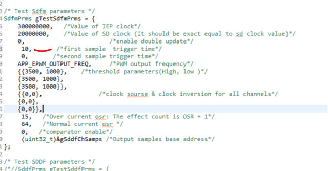
This is not sufficient to make motor is rotating. I supposed that I need to change more things. For example some of SDFM parameters.

How can you help me to change the EPWM frequency in the single chip servo project?

Regards

Kadir


  • I want to update EPWM frequency of Single Chip Servo Project, but when I change only frequency parameters in PWM params and SDDF params, it does not move anymore. This is an urgent issue and I would like to remind that I have been waiting for an answer

  • Hi Kadir,

    Thanks for your query.

    I will check on this and get back to you.

    Best Regards

    Achala Ram

  • Hi Kadir,

    What value are you configuring for first sample trigger time in SDDF params,

    this value should be < 6.2 us {15.62us (EPWM cycle time) - 9.6us (One SDFM sampling time for SINC3 filter, 20MHz SD clock and 64 OSR)}.

    Thanks & regards,

    Achala Ram

  • Hi Achala;

    Thanks for your response. Yes it works when I set it is 6. Could you please share how you calculated it??

     6.2 us {15.62us (EPWM cycle time) - 9.6us (One SDFM sampling time for SINC3 filter, 20MHz SD clock and 64 OSR)}

    Regards

    Kadir

  • Hi Kadir,

    9.6us (One SDFM sampling time for SINC3 filter, 20MHz SD clock and 64 OSR)

    64 OSR and 20 MHz Sigma delta clock are used for sigma delta sampling so the sampling time for one Sigma-Delta sample will be  64*(1/20) us, Since we are using a SIN3 filter, three continuous samples are required for one correct Sigma-Delta sample. Therefore, the total time for one correct Sigma-Delta sample will be 64*(1/20)*3µs, or 9.6 µs.

    You can see Sigma delta firmware doc for more details: https://software-dl.ti.com/processor-industrial-sw/esd/motor_control_sdk/am243x/09_02_00_11/docs/api_guide_am243x/SDFM_DESIGN.html#autotoc_md306

    this value should be < 6.2 us {15.62us (EPWM cycle time)

    EPWM freq. is set to 64K so control loop cycle period will be 15.62us. As for one correct Sigma delta sample 9.6us time is required so you need to start sigma delta sampling 9.6us before the end of control loop cycle (15.62 - 9.6). 

    Thanks & regards,

    Achala Ram  

  • I have tried all values 10, 8, 7 for "first sample trigger time" .And finally it worked when I set it is 6. Therefore it is important for me that the ‘first sample trigger time’ value should be less than 6.2. I understand 9.6 but why this value should be less than 6.2 is still a mystery to me?????????
    Could you please help about this????

  • Hi Kadir, 

    The Sigma delta firmware has a constraint that all three samples must be completed within the control loop cycle period. Therefore, you need to configure trigger point for the first sample in such a way that the third sample is completed before the a control cycle ends (15.62 µs). If the first trigger point is set to a value greater than 6.2 µs, the SDFM firmware will not be able to complete the third sample of the three consecutive samples.

    Thanks & Regards,

    Achala Ram