Part Number: EK-TM4C1294XL
Tool/software:
Hello,
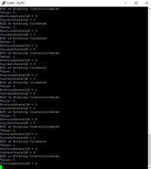
I am trying to program the EK-TM41294XL with an optical encoder loop that will tell me what the value is and what direction the rotary dial is being turned in. I think I initialized GPIO Base Q Pin 2 and Pin 3 correctly, but I am getting incorrect values on the inputs coming in. Am I missing a step? It's just not reading the optical encoder outputs on GPIOL Pin 0 and Pin 1 correctly. I placed the rotary switch on GPIOQ Pin 0 and Pin1
/
//*****************************************************************************
//
// Configure the UART and its pins. This must be called before UARTprintf().
//
//*****************************************************************************
void ConfigureUART(void)
{
//
// Enable GPIO port A which is used for UART0 pins.
// TODO: change this to whichever GPIO port you are using.
//
SysCtlPeripheralEnable(SYSCTL_PERIPH_GPIOA);
//
// Configure the pin muxing for UART0 functions on port A0 and A1.
// This step is not necessary if your part does not support pin muxing.
// TODO: change this to select the port/pin you are using.
//
GPIOPinConfigure(GPIO_PA0_U0RX);
GPIOPinConfigure(GPIO_PA1_U0TX);
//
// Enable UART0 so that we can configure the clock.
//
SysCtlPeripheralEnable(SYSCTL_PERIPH_UART0);
//
// Use the internal 16MHz oscillator as the UART clock source.
//
UARTClockSourceSet(UART0_BASE, UART_CLOCK_PIOSC);
//
// Select the alternate (UART) function for these pins.
// TODO: change this to select the port/pin you are using.
//
GPIOPinTypeUART(GPIO_PORTA_BASE, GPIO_PIN_0 | GPIO_PIN_1);
//
// Initialize the UART for console I/O.
//
UARTStdioConfig(0, 115200, 16000000);
}
void IntHandlerPortQ(void)
{
GPIOIntClear(GPIO_PORTQ_BASE, GPIO_INT_PIN_0 | GPIO_INT_PIN_1);
UARTprintf("RID Switch pressed \n");
UARTprintf("Value is: %d \n", counter);
}
void IntHandlerPortL_RID(void)
{
GPIOIntClear(GPIO_PORTL_BASE, GPIO_INT_PIN_2 | GPIO_INT_PIN_3);
}
void Port_Init(void)
{
GPIOPinTypeGPIOInput(GPIO_PORTL_BASE, (GPIO_PIN_0 | GPIO_PIN_1));
GPIOPinTypeGPIOInput(GPIO_PORTQ_BASE, (GPIO_PIN_0 | GPIO_PIN_1));
GPIOPadConfigSet(GPIO_PORTQ_BASE, (GPIO_PIN_0 | GPIO_PIN_1), GPIO_STRENGTH_10MA, GPIO_PIN_TYPE_STD);
GPIOPadConfigSet(GPIO_PORTL_BASE, (GPIO_PIN_0 | GPIO_PIN_1), GPIO_STRENGTH_10MA, GPIO_PIN_TYPE_STD);
GPIOIntTypeSet(GPIO_PORTQ_BASE, (GPIO_PIN_0 | GPIO_PIN_1), GPIO_RISING_EDGE);
GPIOIntTypeSet(GPIO_PORTL_BASE, (GPIO_PIN_0 | GPIO_PIN_1), GPIO_RISING_EDGE);
GPIOIntRegister(GPIO_PORTQ_BASE, IntHandlerPortQ);
GPIOIntRegister(GPIO_PORTL_BASE, IntHandlerPortL_RID);
GPIOIntEnable(GPIO_PORTQ_BASE, (GPIO_INT_PIN_0 | GPIO_INT_PIN_1));
GPIOIntEnable(GPIO_PORTL_BASE, (GPIO_INT_PIN_0 | GPIO_INT_PIN_1));
}
void ReadRIDPosition(void)
{
previousStateCLK = GPIOPinRead(GPIO_PORTL_BASE, GPIO_PIN_3);
// Read the current state of inputCLK
currentStateCLK = GPIOPinRead(GPIO_PORTL_BASE, GPIO_PIN_3);
// If previous and current state of the inputCLK are different then a pulse has occurred
if (currentStateCLK != previousStateCLK)
{
UARTprintf("CurrentStateCLK = %d \n", currentStateCLK);
// If the inputDT state is different than the inputCLK state then the encoder is rotating counterclockwise
if (GPIOPinRead(GPIO_PORTL_BASE, GPIO_PIN_2) != currentStateCLK)
{
counter--;
UARTprintf("RID is Rotating Counterclockwise \n");
//
// Turn on the LED1 for CCW
//
GPIOPinWrite(GPIO_PORTN_BASE, USER_LED1, USER_LED1);
//
// Turn off the LED2 for CW
//
GPIOPinWrite(GPIO_PORTN_BASE, USER_LED2, 0x0);
}
else
{
// Encoder is rotating clockwise
counter++;
UARTprintf("RID is Rotating Clockwise \n");
//
// Turn on the LED2 for CW
//
GPIOPinWrite(GPIO_PORTN_BASE, USER_LED2, USER_LED2);
//
// Turn off the LED1 for CCW
//
GPIOPinWrite(GPIO_PORTN_BASE, USER_LED1, 0x0);
}
// Output value
UARTprintf("Value: %d \n", counter);
if(GPIOPinRead(GPIO_PORTQ_BASE, GPIO_PIN_0 | GPIO_PIN_1) == 0)
{
UARTprintf("Value is: %d \n", counter);
}
// Updated previousStateCLK with the current state
previousStateCLK = currentStateCLK;
UARTprintf("PreviousStateCLK = %d \n", previousStateCLK);
}
}
//*****************************************************************************
//
// The interrupt handler for the for I2C0 data slave interrupt.
//
//*****************************************************************************
/*void
I2C0SlaveIntHandler(void)
{
//
// Clear the I2C0 interrupt flag.
//
I2CSlaveIntClear(I2C0_BASE);
//
// Read the data from the slave.
//
g_ui32DataRx = I2CSlaveDataGet(I2C0_BASE);
//
// Set a flag to indicate that the interrupt occurred.
//
g_bIntFlag = true;
}
*/
//*****************************************************************************
//
// Toggle a GPIO.
//
//*****************************************************************************
int
main(void)
{
//
// The I2C0 peripheral must be enabled before use.
//
// SysCtlPeripheralEnable(SYSCTL_PERIPH_I2C0);
//
// Enable the GPIO module.
//
SysCtlPeripheralEnable(SYSCTL_PERIPH_GPIOQ);
while(!SysCtlPeripheralReady(SYSCTL_PERIPH_GPIOQ));
SysCtlPeripheralEnable(SYSCTL_PERIPH_GPIOL);
while(!SysCtlPeripheralReady(SYSCTL_PERIPH_GPIOL));
SysCtlPeripheralEnable(SYSCTL_PERIPH_GPIOA);
while(!SysCtlPeripheralReady(SYSCTL_PERIPH_GPIOA));
//
// Enable and wait for the port to be ready for access
//
SysCtlPeripheralEnable(SYSCTL_PERIPH_GPION);
while(!SysCtlPeripheralReady(SYSCTL_PERIPH_GPION));
SysCtlDelay(1);
//
// Configure the device pins.
//
PinoutSet(false, false);
//
// Configure the GPIO port for the LED operation.
//
GPIOPinTypeGPIOOutput(GPIO_PORTN_BASE, (USER_LED1 | USER_LED2));
//
// Run from the PLL at 120 MHz.
//
g_ui32SysClock = SysCtlClockFreqSet((SYSCTL_XTAL_25MHZ |
SYSCTL_OSC_MAIN | SYSCTL_USE_PLL |
SYSCTL_CFG_VCO_480), 20000000);
//
// Configure the UART.
//
ConfigureUART();
Port_Init();
SysCtlDelay(1);
while (1)
{
ReadRIDPosition();
}
}