Other Parts Discussed in Thread: AM263P4, SYSCONFIG, AM2634
Tool/software:
Hi,
I'm using the AM263P4 ZCZ_C package (AM263x pin compatible) together with the S25FL128S flash IC (same used on AM263x launchpad) on custom hardware.
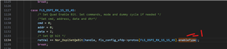
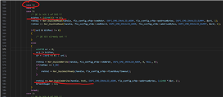
I'm having issues with trying to read/write to the flash with the OSPI in 4S mode. I can read/write the bootloader and application in 1S mode without any issues, however cannot do so with the 4S OSPI settings.
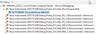
Additionally, the bootloader is only loaded from flash when the SOP pins are in 1S mode, it does not work in 4S mode. This seems to suggest that the issue is in hardware, rather than software.
Can you confirm if there are any issues with running the ZCZ_C package in 4S mode or if there are compatibility issues with the flash used in previous launchpad development boards?
Thanks,
Carwyn