This thread has been locked.

If you have a related question, please click the "Ask a related question" button in the top right corner. The newly created question will be automatically linked to this question.

LP-AM243: Converting SDFM Output Data to Amps

Part Number: LP-AM243
Other Parts Discussed in Thread: BP-AM2BLDCSERVO, , AMC1035

Tool/software:

Hello,

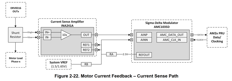
    I am working with the LP-AM243 in combination with the BP-AM2BLDCSERVO booster pack to control two BLDC motors. I have successfully setup the 'single_chip_servo' example from the Motor Control SDK V9.2.0.9 and have been working towards fully understanding the configuration and usage of the sigma delta current measurement. One aspect I can't seem to figure out is how to correctly convert the output data from the SDFM firmware to Amps. In the single chip servo example a ratio is created based on the output range and then that value is multiplied by 30, but I cant figure out where that value of 30 comes from. Here is the information I have found:

  • The output range of the SDFM firmware is -131072-131072 with an OSR of 64
  • AMC1035 full scale voltage range is -1.25V-1.25V
  • INA241 gain is 10x
  • Shunt resist for Booster Pack is 0.01ohm

So the calculation I would expect to covert to Amps would be:  ((Output-131072) / 131072) * 1.25V / 10 / 0.01ohm    -or-     ((Output-131072) / 131072) * 12.5

What am I missing? Does the SDFM firmware do some conversion internally first?

Also, could someone please explain why the SDFM firmware output value range changes based on OSR? This would be greatly appreciated.

  • Hi Antonio,

    Does the SDFM firmware do some conversion internally first?

    No, It does not do any conversion, Firmware writes raw data (Filters output) into memory which R5 reads.

     Here is the method to convert SDFM output to amps,

     assume you refer to BP-AM2BLDCSERVO kit which has following current sense design.

    The equation depends on shunt resistor and OSR of sinc3 filter.

    Example:

    - shunt resistor: 1 mOhm (variable)

    - INA241 gain: 10 (fixed)

    - AMC1035D input: +- 1.0V (fixed)

    The configuration can measure +-100A which corresponds to the full scale of data conversion.

    With OSR64 (variable) sinc3 filter full scale is: 64*64*64 = 262144.

    Isense = (200A ∗ Ipru)/262144 − 100A

    Ipru is the output of the sigma delta filter.

    Isense is the measured current in A.

    Note: there has been different hardware revisions of the booster-pack with different shunt resistor values. The values of the resistor also depends on the max current you want to drive with your application (motor).

    Thanks & RegardIs,

    Achala Ram

  • Thank you Achala, this confirmed my understanding of the circuitry and sparked me to check the resistor value of the physical board I have. Although the board I have is Rev E2 and the schematic I have is Rev E2, the schematic indicates a 10mOhm shunt resistor should be present while the board actually has the 1mOhm resistor you mentioned. This explains the discrepancy in my measurements versus my calculations.