This thread has been locked.

If you have a related question, please click the "Ask a related question" button in the top right corner. The newly created question will be automatically linked to this question.

[FAQ] LP-AM243: Routing GPIO interrupts to PRU core

Part Number: LP-AM243
Other Parts Discussed in Thread: SYSCONFIG

Tool/software:

I am trying to modify the gpio_input_interrupt example for the R5F0-0 core to direct the GPIO interrupt to the PRU core.

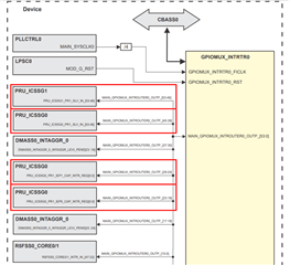
Requirement: GPIO1_0 interrupt ->  MAIN_GPIOMUX_INTROUTER0_OUTP_18 -> IEP0_CAP

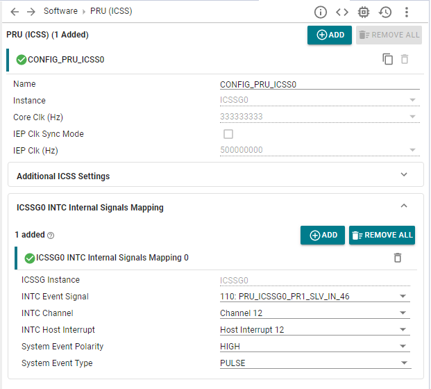
SysConfig does not seem to allow the configuration of PRU specific MAIN_GPIOMUX_INTROUTER_OUTP, as the only visible options for interrupt router output are MAIN_GPIOMUX_INTROUTERS[0:7].

As a workaround, I copied files generated from the syscfg file and tried to modify the rmIrqReq.dst_host_irq parameter in the Sciclient_gpioIrqSet function manuallybut this also doesn't work and results in a Sciclient error.

How can I solve this problem ?

  • Although many output pins are available for the GPIO MUX interrupt router, only resource pin that are allocated in board configuration is available for use in the Sysconfig GUI, i.e. MAIN_GPIOMUX_INTROUTER0_OUTP_[0:7].

  • To achieve the above use case, follow the steps below:

    Step 1: Modify the application

    i. Locate the application functions calling Sciclient_gpioIrqSet and Sciclient_gpioIrqRelease (functions Board_gpioInit() and Board_gpioDeinit()), copy the content of these functions to new functions and make the below changes

    rmIrqReq.dst_id = TISCI_DEV_PRU_ICSSG0;
    rmIrqReq.dst_host_irq = CSLR_PRU_ICSSG0_PR1_SLV_INTR_MAIN_GPIOMUX_INTROUTER0_OUTP_38;

    ii. Replace the existing function call to Board_gpioInit()/Board_gpioDeinit() with the new functions (add the required #define to the application as well).

    iii. Sysconfig settings should be as following:

    Step 2: Modify Board cfg for resource allocation 

    Locate sciclient_defaultBoardcfg_rm.c file at <mcu_plus_sdk>\source\drivers\sciclient\sciclient_default_boardcfg\am243x

    For the above usecase, make the below changes to the rm cfg file:

    i. Add an entry for a new TISCI_DEV_MAIN_GPIOMUX_INTROUTER0 with the start resource as 18 (PRU_ICSSG0_PR1_IEP0_CAP_INTR_REQ0 interrupt input line is mapped to source interrupt MAIN_GPIOMUX_INTROUTER0_OUTP_18)

    {
        .num_resource = 1,
        .type = TISCI_RESASG_UTYPE (TISCI_DEV_MAIN_GPIOMUX_INTROUTER0, TISCI_RESASG_SUBTYPE_IR_OUTPUT),
        .start_resource = 18,
        .host_id = TISCI_HOST_ID_MAIN_0_R5_1,
    },

    ii. Increase the resasg_entries_size by 1 to reflect the new added resource.

    .resasg = {
        .subhdr = {
            .magic = TISCI_BOARDCFG_RM_RESASG_MAGIC_NUM,
            .size = (uint16_t) sizeof(struct tisci_boardcfg_rm_resasg),
        },
        .resasg_entries_size = 166 * sizeof(struct tisci_boardcfg_rm_resasg_entry), // increased from 165 to 166
    },

    SCI client parameters are configured based on this documentation: https://software-dl.ti.com/tisci/esd/latest/5_soc_doc/am64x/interrupt_cfg.html

    Alternatively, you can also use the rm cfg tool for resource allocation as well, please refer to the MCU+doc for more information - https://software-dl.ti.com/mcu-plus-sdk/esd/AM243X/09_02_00_50/exports/docs/api_guide_am243x/RESOURCE_ALLOCATION_GUIDE.html

    Step 3: Rebuild the board configuration and SBL

    Navigate to the SDK root directory

    Re-build the sciclient_ccs_init example and the boardcfg binary blob by running the below command (This makes sure that boardcfg is updated for both SBL and CCS based boot flows)

    make -s -C tools/sysfw/boardcfg sciclient_boardcfg SOC=am243x

    Re-compile the SBL by running the below commands:

    gmake -s sbl clean 
    gmake -s sbl 
    gmake -s sbl PROFILE=debug clean
    gmake -s sbl PROFILE=debug 


    Step 4: Flash the board with the updated SBL

    Replace the sbl image present in <mcu_plus_sdk>/tools/boot/sbl_prebuilt/am243x-lp/ with the new generated <sbl>.release.hs_fs.tiimage in <mcu_plus_sdk>\examples\drivers\boot\<sbl>\am243x-lp\r5fss0-0_nortos\ti-arm-clang

    Flash your board with the new sbl image, following the steps here - FLASH_SOC_INIT

    Power up the board and load the example from CCS.

    Regards,

    Nitika