This thread has been locked.

If you have a related question, please click the "Ask a related question" button in the top right corner. The newly created question will be automatically linked to this question.

AM263P4: AM263P4 Control Card - Boot from QSPI

Part Number: AM263P4
Other Parts Discussed in Thread: UNIFLASH, AM2634

Tool/software:

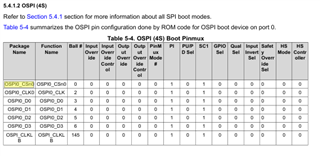
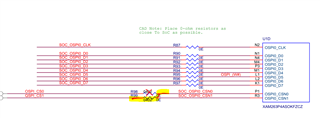
I am trying to launch my sbl and application from QSPI on the PROC159E2 AM263P4 Control Card.     I have successfully programmed and booted from OSPI on this board.      I appears that OSPI is selected by default ,   with Resistor R1679, which sets the OSPI/QSPI Mux Select.     I need to use a QSPI part for my application, and not OSPI.

I have done the following.....

      1.   I have DNP'd R1679,  and added a resistor to R3836 instead,  to pull this mux low at Startup, before any code has executed.       

      2.   I used QSPI settings from ospi_nand_flash_io example to convert sbl_null_am263px from OSPI to QSPI.     

      3.   I tried using the uniflash app and a modified flasher_jtag_uniflash to  program the QSPI and it will not work.  I can open flash successfully,  but the uniflash programmer will not program to qspi for some reason.

      4.   I tried a modified version of sbl_uart_uniflash and the python script uart_uniflash.py ,   and successfully can program to QSPI flash.    The response header has status code 0 = SUCCESS.    I can use this script to     program anything I want to the QSPI part.

This is where I am stuck.    I am looking for an example of a program that will successfully launch from QSPI which doesn't use XIP as I understand it.      This is very difficult to debug since I just have to reboot with the correct  boot mode selection, and hope for the best.     I can't get any program to launch from QSPI.      I am guessing this is because the memory settings are not correct.  Would love a working example that boots from QSPI.     

Thanks,

   Russ


  • Hi Russ, our expert for this topic is out of office and will return by 31st Dec, please expect a response early that week.

    Regards,

    Sahana

  • Any updates ?,   we are trying to design a circuit board currently,  and this issue is critical to the hardware design?

    Thanks, 

        Russ   

  • Hi Russ,

    Sorry for the delay.

    appears that OSPI is selected by default ,   with Resistor R1679, which sets the OSPI/QSPI Mux Select.     I need to use a QSPI part for my application, and not OSPI

    Yes, this is one change that needs to be done. Apart from this we will have to ensure that the OSPI0_CSN0 is connected to QSPI_CS1.This is because ROM uses OSPI0_CSn0 ball pin for Boot. Please refer to section 5.4.1.2 OSPI (4S) in AM263P TRM.


    As a HW workaround you can DNI R98 and do a criss-cross connection to R99 for connecting the OSPI0_CSN0 to QSPI_CS1.


    Thanks & Regards,
    Rijohn

  • I have performed the suggested hardware mod, and modified my uart flasher program to use CS0.    I am able to program using the new modification,  but unable to boot.     Can you recommend a program from the SDK that has the correct ram settings to boot from QSPI without XIP.   For example,  I have tried booting sbl_null_am263px    with no luck.        

  • On an unmodified Control Card board,   I have verified that when programming OSPI,  I can program sbl_null_am263px successfully, and then successfully launch that program.      

  • Hi Russell,

    Which QSPI part are you planning to use. We are internally working with our team to debug this issue. We will keep you posted on updates.

  • I have made progress on Booting from QSPI with the following steps.

    1. I removed the Windbond W25 QSPI Flash,  and installed the Infineon S25FL128L series SOIC 8 part,  which fits in the same location as the WSON part,  and is the same pinout.    
    2. Performed the Chip Select Modification mentioned above so the QSPI part is connected to AM263P Chip Select 0.
    3. Place AM263P in UART bootmode ,  and programed using the python uart_uniflash.py script and the sbl_uart_uniflash application programmed for 1S QSPI parameters.    
    4. programmed my app and a modified sbl_ospi bootloader to use 1S QSPI
    5. Place the processor in QSPI (1S) 50Mhz mode

    The hardest part was modifying the OSPI settings for the new part.   I had to mess with the settings with a logic analyzer on the spi lines until I could program the part.   

    The application will only launch in 1S mode with this memory ,  with either 1S QSPI,  or xSPI mode, which also boots in 1S mode.    
    I have not gotten write or read in 4S mode to work yet, and it appears not so boot in 4S mode anyway.    
    Boot time of SBL and typical application is around 200 ms.   This would be much faster in 4S mode, but it works.     

  • Hi Russell,

    Thank you for debug summary.

    We recreated setup on AM263x Control Card + AM263P_ZCZ_C Si. And for me the RBL is reaching at the SBL Confirming RBL boot is successful and no HW issues.

    Here I had flashed the sbl image and hello_world app image  in mcu_plus_sdk_am263x_10_01_00_31 using AM2634 and then changed the sample to AM263Px. And booted in OSPI (4s) boot mode. PC location = 0x7012BA84 indicating RBL boot is successful.


    We are working with the SDK team internally to check for the support of this QSPI flash in SBL. I will get back on this

    Thanks & Regards,
    Rijohn

  • The S25FL128L Series boots in 1S mode for me in both ( 1S boot option, or in xSPI boot option) , but doesn't boot in 4S mode.   We would like to speed up booting with 4S mode if possible.    I have it hooked up to a logic analyzer, so I export the boot sequence in 4S mode if needed.  

    S25FL128LAGMFM010 is our preferred part.

  • Hi Russell,

    Please use the S25128L configuration json file in your example, we have tested on our end it is working