This thread has been locked.

If you have a related question, please click the "Ask a related question" button in the top right corner. The newly created question will be automatically linked to this question.

MSPM0L1306: How to make C1 of TMIG4 a complementary output

Genius 3215 points

Part Number: MSPM0L1306
Other Parts Discussed in Thread: SYSCONFIG

Tool/software:

Hi All,

C0 of TMIG4 is a positive output and C1 is a complementary output.
The complementary output is used to set the deadband by changing the duty cycle.
Currently, the initial output is Low for both C0 and C1.
Is there any way to suppress the initial output of C1?

Best Regards,

Ito

  • Hi Ito,

    TIMG does NOT support complementary output in hardware. Only TIMA series timer support this feature.

    I assume you are using the software solution:

    1. set the C0 initial status as low / set the C1 as high by below API

    2. set a complementary behavior when CTR reaches the CC value (CC EVENT); also with the ZERO or LOAD event.

    2. When set the duty, make sure you proper handle the offset according to your deadtime requirement.

    B.R.

    Sal

  • Hi Sal,

    Thank you very much.

    Which items should I check when configuring in Sysconfig?

    Best Regards,

    Ito

  • Hi Ito,

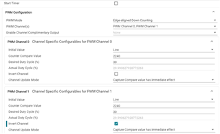
    Here set the initial value:

    For the event behavior, user should manually modify it in application code:

    The sysconfig generated code will auto set the event behavior.

    B.R.

    Sal

  • Hi Sal,

    Thank you for your help.

    The TRM has a description of ”Complementary PWM output with programmable deadband insertion” only for TIMA.
    I understand that this means that the deadband can be set by register operation, not that the complementary output is not possible with TIMG.

    In fact, when I checked the waveforms, I succeeded in setting the deadband by adjusting the complementary output and the duty cycle of C0 and C1.

    If I can suppress the first Low to High part, the problem will be solved, but is there any way to do it?

    First I would like to check if it is really possible to set up complementary outputs in TIMG, then I would like to set them up in TIMA.

    Best Regards,

    Ito

  • Hi Sal,

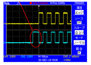
    I want to create a waveform like the following.


    I have heard that in C2000, there is a way to suppress the output by matching the counter value at timer startup with the complementary side compare match value.

    Best Regards,

    Ito

  • Hi Sal,

    Is it possible to make it look like the image (green waveform) in TIMG?
    Please answer this question.

    Best Regards,

    Ito

  • Hi Sal,

    Please answer this question.

    Ito

  • Hi KZ,

    Sorry for the delay. I am on business travel this week, so I need back to office and update in early next week. Thanks for your patience.

    B.R.

    Sal

  • Hi Sal,

    Thank you for your reply.

    I'm sorry to rush you.

    Best regards,

    Ito

  • Hi Sal,

    We are checking if it is possible to suppress the initial output of C1 by setting the compare match value to the initial value of the timer counter.
    As a result of this work, the initial output of C1 could not be suppressed, but Duty could be controlled.

    ・The complementary side's compare match value is set to the timer counter immediately after the timer is started by DL_TimerG_startCounter.
    ・DL_TimerG_startCounter clears the timer counter value, so the counter value is updated after the timer starts.

    xxx is added to check the acquired compare match value

    uint32_t xxx = 0;

    int main(void)
    {
    SYSCFG_DL_init();

    xxx = DL_TimerG_getCaptureCompareValue(PWM_0_INST, DL_TIMER_CC_1_INDEX);
    DL_TimerG_startCounter(PWM_0_INST);
    DL_TimerG_setTimerCount(PWM_0_INST, xxx);

    while (1) {
    __WFI(); 

    }
    }

    If I can suppress the initial output of C1, the problem is solved.

    Best Regards,

    Ito

  • Hi KZ,

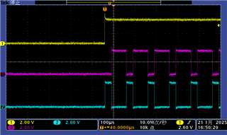
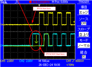
    One things might need you conrimation. When I just set the invert functions, I see its output is correct:

    Yellow line is the timing of the PWM start. And Bule line is C1 (TIMG0, PA13), Purple line is C0 (TIMG0, PA12).

    I just invert the C1 in sysconifg:

    ======================================================================

    [Actually, if you switch the C0 and C1, you will find it is the exact waveform you want.]

    ======================================================================

    If you do need to suppress the output, then use below API:

    Example:

    //    DL_Timer_overrideCCPOut(TIMG4, DL_TIMER_FORCE_OUT_LOW, DL_TIMER_FORCE_CMPL_OUT_LOW, DL_TIMER_CC_1_INDEX);

    You need to release manually in the code when you need it output.

    B.R.

    Sal

  • Hi Sal,

    Thank you for your help.

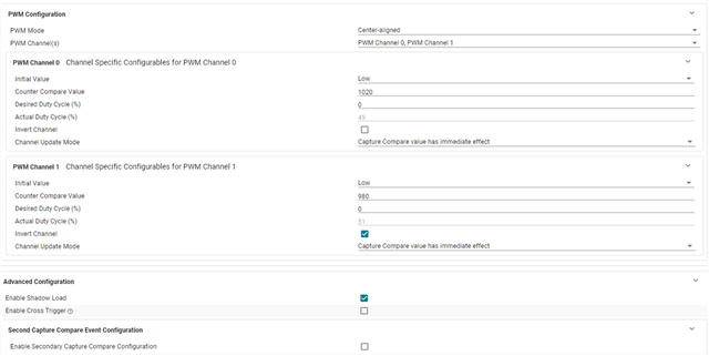
    Customer was using Center-aligned instead of Edge-aligned to set deadtime with different Duty for C0 and C1.

    Is it possible to get the desired waveform even with center-aligned?

    Also they try TIMA settings.

    Can you show me a screenshot of the Sysconfig setup  to produce the above complementary waveforms in TIMA?

    Best Regards,

    Ito

  • Hi KZ,

    For TIMA, set the below:

    And, actually the original waveform is correct. That is the complementary waveform.

    The waveform you want is not a complementary PWM, if you capture the timing of the PWM generation.

    If you do want this: Invert C0 rather than invert C1.

    B.R.

    Sal

  • Hi Sal,

    Thanks for providing the waveform.

    Is Center-aligned PWM Mode okay?

    Best Regards,

    Ito

  • Hi Ito,

    Yes, it could work.

    If you do want this: Invert C0 rather than invert C1.

    As I showed previous.

    B.R.

    Sal