Other Parts Discussed in Thread: EK-TM4C1294XL
Tool/software:
Hi - I've got an EK-TM4C129EXL and an EK-TM4C1294XL. I'm using the EK-TM4C129EXL to update the firmware on the EK-TM4C1294XL over I2C using the ROM bootloader.
I've read the "TivaWare Boot Loader User's Guide" (SPMU301E) numerous times in great detail and believe I am doing everything correctly. For example:
- I setup I2C in slave mode on the EK-TM4C1294XL before disabling interrupts and calling ROM_UpdateI2C().
- I setup I2C in master mode at 100 kbps on the EK-TM4C129EXL and make sure the EK-TM4C1294XL has called ROM_UpdateI2C() before attempting to send commands.
The steps I'm performing on EK-TM4C129EXL to send the firmware to the EK-TM4C1294XL are as follows. First I send the COMMAND_DOWNLOAD command using the following steps:
- Send a COMMAND_DOWNLOAD command appropriately packetized. (I write the firmware to address 0x00000000 since I do not have my own bootloader and the size of the new firmware is 0x9A8)
- Check for the ACK to the COMMAND_DOWNLOAD command
- Send COMMAND_GET_STATUS appropriately packetized.
- Check for the ACK to the COMMAND_GET_STATUS command
- Make sure the return code from COMMAND_GET_STATUS is COMMAND_RET_SUCCESS.
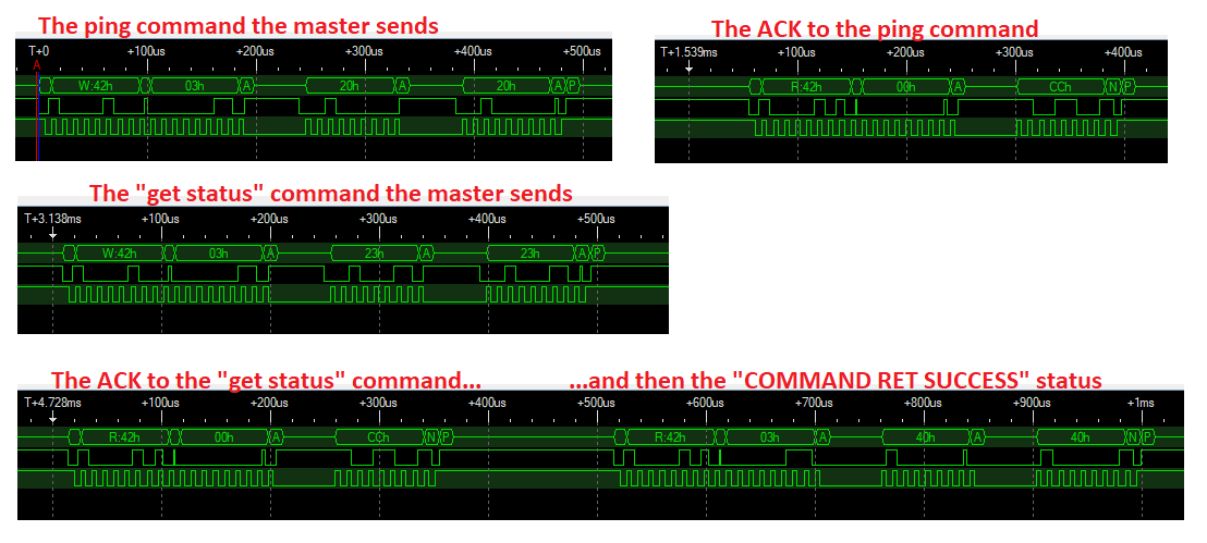
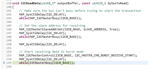
The following are images from my logic analyzer showing the successful communication of the steps above. First the COMMAND_DOWNLOAD and then starting to read the ACK...
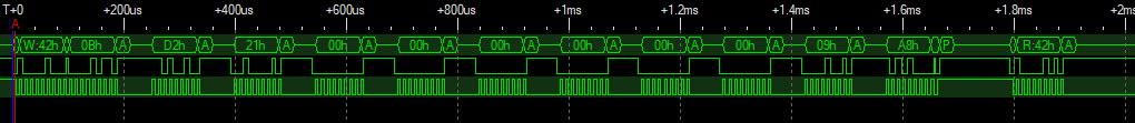
...and then the ACK response, and the status:

All of it looks good.
I then wait 10 seconds (yes, 10 full seconds) since I know the COMMAND_DOWNLOAD step needs to erase the entire flash section on the EK-TM4C1294XL.
Then I start with my COMMAND_SEND_DATA commands:
- Send a COMMAND_SEND_DATA command appropriately packetized.
- Check for the ACK to the COMMAND_SEND_DATA command
- Send the COMMAND_GET_STATUS command appropriately packetized.
- Check for the ACK to the COMMAND_GET_STATUS command
- Make sure the return code from COMMAND_GET_STATUS is COMMAND_RET_SUCCESS.
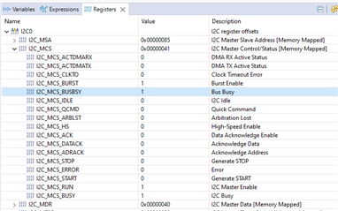
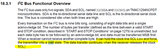
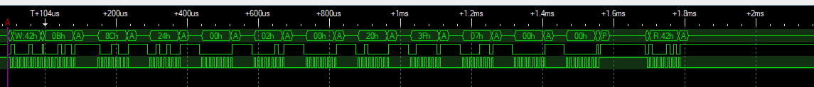
When doing the first COMMAND_SEND_DATA command it hangs indefinitely at step 2. The bootloader never sends back an ACK no matter how long I wait. Here's my logic analyzer output:
Now, here's the funny thing: If I omit the COMMAND_GET_STATUS when doing both the COMMAND_DOWNLOAD and COMMAND_SEND_DATA commands, everything works. The entire 0x9A8 bytes of the new firmware will successfully get sent from the EK-TM4C129EXL to the EK-TM4C1294XL and written to flash on the EK-TM4C1294XL. When rebooting, it successfully runs the new firmware.
So, I'm confused on two points and hoping someone has some suggestions:
- Why is the I2C communication hanging after that first COMMAND_SEND_DATA command.
- Why does everything work when removing the COMMAND_GET_STATUS commands.
Any suggestions would be appreciated. Thanks.
-Terence