This thread has been locked.

If you have a related question, please click the "Ask a related question" button in the top right corner. The newly created question will be automatically linked to this question.

MSPM0G1506: Application update fails using UART BSL

Part Number: MSPM0G1506
Other Parts Discussed in Thread: LP-MSPM0G3507, UNIFLASH, , MSPM0G3507

Tool/software:

Hello,

I tried to update a MSPM0G controller via UART. As flash master I use the TI Evalboard LP-MSPM0G3507 which I connected to my PC via USB.

I used the BSL_GUI_EXE V1_2 from the SDK mspm0_sdk_2_03_00_07. 

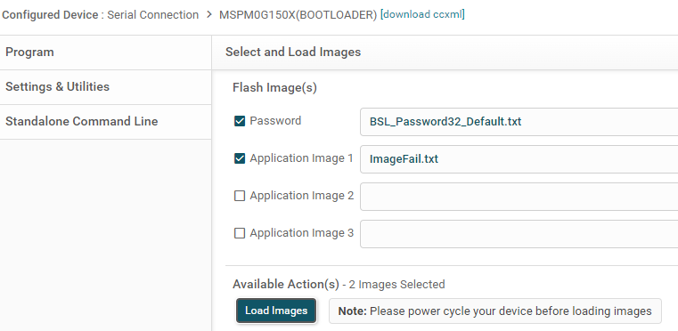
This had worked without errors before but now I found out that some applications are not flashed completely. The GUI says firmware sent successfully, an error is displayed though:

I read the memory of the target controller after the failed update via debugger and saw that the first 16 bytes and the last 32 bytes were not written.

So, I tried to compare the differences between the firmware images that could be flashed without errors and the ones that were not flashed completely.

I removed some random code from the software that could not be flashed so that it is a little bit smaller. The smaller image can be flashed, the bigger image not.

End of smaller image:

End of bigger image:

Is it possible that some parts of the memory must not be written? (Maybe when address 0x6400 is exceeded?? Something with the alignment??)

Or is there maybe a bug/timeout in the GUI?

My assumption that this issue has something to do with the size of the firmware could be totally wrong, but I am pretty sure that the code which I removed in my software should not be responsible for flash fails.

Please let me know what could be the root cause for this and how to solve this.

Thanks in advance and best regards, 

Fabian

  • Hi Fabian,

    I have not seen this issue previously, have you tried utilizing the Uniflash tool as your BSL host to see if this flash programming succeeds for all memory locations?

    I do not see any issue with the memory locations you are using. As for your program size, the tool should support programs that span the entirety of the devices flash, so one extending up to 0x6400 should not be an issue. 

    Could you try with another BSL host like Uniflash mentioned above and let me know the results? This will tell us if the issue is in the BSL GUI tool.

    Additionally just to clarify, you are interfacing the BSL GUI with the LP-MSPM0G3507, correct?

  • Hi Dylan,

    Thanks for your reply! Yes, I use the BSL GUI with the LP-MSPM0G3507 to flash a MSPM0G1506 controller as target.

    I must admit that host and target are not connected directly over UART. Instead we have a LIN transceiver on each end to transmit data via LIN. Therefore we had to implement a filter on the MSPM0G3507 on the EvalBoard which cuts off the echo from the LIN transceiver.

    This is the concept:

    How can I use this Uniflash with the same setup? I tried the following configuration but that didn't work:

    Before the update I erased the target via debugger. So the controller should enter BSL after power cycle and use default UART pins PA10/PA11.

    What am I doing wrong?

    Best regards,

    Fabian

  • Thank you for the information here. I see your setup diagram and this is helpful, but I am a little unclear on your implementation. If the LP-MSPM0G3507 is behaving as the BSL host that is transmitting the program data to the MSPM0G1506, that should be fine. But if this was the case, I do not see the need for the BSL GUI to be running on your PC. Are you using the BSL GUI to flash the LP-MSPM0G3507 with another BSL host program, then using the LP to flash the MSPM0G1506? 

    I am just missing why the GUI is needed when you have the LP functioning as the BSL host. Maybe if you could tell me what software is running on the LP to explain? Are you using an example?

    My expectation with the BSL GUI is that you connect the PC to the launchpad, and in that case the launchpad is the BSL target device. Then by programming with the GUI, you are flashing the LP. The GUI isn't working with the assumption that the Launchpad is then connected to a target device.
    Sorry to keep returning with questions, I am just a bit confused at the steps you are taking and what your intended behavior is. In my view it currently looks like you have 2 BSL hosts and 1 target.

  • Ah, maybe my explanation was a bit confusing. Sorry for that! I try it again: 

    My PC (running the GUI) is the BSL host to flash the MSPM0G1506 on the target PCB.

    On the MSPM0G3507 of the LP runs an application that I flashed via debugger. This application forwards the data on the UART RX/TX and cuts off the echo from the LIN transceiver. It is necessary because the echo was interpreted as an invalid answer by the host. So, I would say the LP is not a 2nd BSL host but rather a helper and gateway for the BSL host on the PC.

    I hope, this helps ypu to understand my setup. If not, let me know. Or maybe you have a suggestion how to it better.

    This setup works fine, but as I described in the original post: The update fails sometimes because the firmware is not written completely.

  • Oh I understand now, thank you for clarifying.

    I would think that you could use the Uniflash tool in the same way, since your LP is just forwarding the data to the target device. Maybe the responses from the target are not getting back to the Uniflash tool, causing that error.

    Anyways, my concern here would be whether the LP is forwarding all of the correct data, have you tried probing the UART between the LP and the target, and making sure that the data matches the data between the PC and the LP? This could tell us if the error comes from the LP or the GUI.

    I'd also like to ask if you have tried using an alternative implementation - you could wire the XDS110 UART on the Launchpad directly to the target device, bypassing the MSPM0G3507 on the Launchpad. Then the BSL GUI is communicating directly with the target device. This would result in a simpler system with fewer points of potential failure. Have you tried this / is this a possibility? I would highly recommend using this simpler set-up if possible.

  • Good news: I found the reason for this problem.

    I still couldn't get the Uniflash to work, instead I kept using the BSL GUI and my approach was to find out which error code is actually sent by the target. So, I recorded the TX and RX data on the UART of the LP.

    The GUI (host) sends the command: 0x80 0x21 0x00 0x20 0x10 0x64 0x00 0x00 | Flash Data 0..27 | CRC 0..3

    Interpretation: 0x80 = Header, 0x0021 = 33 BSL Core Data Byte to be followed, 0x20 = CMD Program Data, 0x00006410 = Flash address

    The BSL (target) responses to this command: 0x00 0x08 0x02 0x00 0x3B 0x0A 0x26 0xEB 0x41 0x62

    Interpretation: 0x00 = BSL acknowledge, 0x08 = Header, 0x0002 = 2 BSL Core Data Byte to be followed, 0x3B = Response Message, 0x0A = Invalid address or length alignment, 0x6241EB26 = CRC

    Then I read in the bootloader guide that the flash data must be 8 byte-aligned. So, this error does make sense, because in the command before there are 28 flash data bytes, which  is not 8-byte aligned. When I add 4 bytes 0xFF to the end of the image (the txt file) manually, it works. The update runs without errors. Now, I just need a good solution to add these alignment bytes either in the linker script or in the batch file generating this txt file from the hex file.

  • Thanks for posting your resolution to the issue here, Fabian.

    As for padding your image to align correctly - what tools are you using to build the image that you are flashing? The default settings for examples imported from our SDK to CCS, IAR, Keil, should already be configured for 8 byte alignment.

  • I use Keil to build the hex file. For conversion to txt file, which is required as input for the BSL GUI, I use srec_cat with the following command:

    srec_cat.exe %inputFile% -intel -fill 0xff -within %inputFile% -intel -range-padding 8 -o %outputFile% -TI-TXT

    Executing this command generates an 8-byte aligned image in TI-TXT format.

    Where can I configure the alignment in Keil? I haven't found an option in the Keil project settings.

  • This would be specified in your Keil Scatter file. It looks like you can just use the:

    ALIGN 8 

    Operand inside of your scatter file to specify 8 byte alignment.