Part Number: TM4C1294NCPDT
Tool/software:
Hi Team,
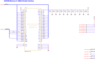
I trying to up EPI0 module communicated with external SDRAM
Following is the code iam using to test in TM4C1294NCPDT
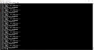
but it always stuck here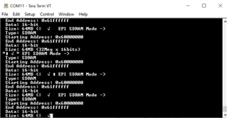
//*****************************************************************************
//
// sdram.c - Example demonstrating how to configure the EPI bus in SDRAM
// mode.
//
// Copyright (c) 2014-2020 Texas Instruments Incorporated. All rights reserved.
// Software License Agreement
//
// Redistribution and use in source and binary forms, with or without
// modification, are permitted provided that the following conditions
// are met:
//
// Redistributions of source code must retain the above copyright
// notice, this list of conditions and the following disclaimer.
//
// Redistributions in binary form must reproduce the above copyright
// notice, this list of conditions and the following disclaimer in the
// documentation and/or other materials provided with the
// distribution.
//
// Neither the name of Texas Instruments Incorporated nor the names of
// its contributors may be used to endorse or promote products derived
// from this software without specific prior written permission.
//
// THIS SOFTWARE IS PROVIDED BY THE COPYRIGHT HOLDERS AND CONTRIBUTORS
// "AS IS" AND ANY EXPRESS OR IMPLIED WARRANTIES, INCLUDING, BUT NOT
// LIMITED TO, THE IMPLIED WARRANTIES OF MERCHANTABILITY AND FITNESS FOR
// A PARTICULAR PURPOSE ARE DISCLAIMED. IN NO EVENT SHALL THE COPYRIGHT
// OWNER OR CONTRIBUTORS BE LIABLE FOR ANY DIRECT, INDIRECT, INCIDENTAL,
// SPECIAL, EXEMPLARY, OR CONSEQUENTIAL DAMAGES (INCLUDING, BUT NOT
// LIMITED TO, PROCUREMENT OF SUBSTITUTE GOODS OR SERVICES; LOSS OF USE,
// DATA, OR PROFITS; OR BUSINESS INTERRUPTION) HOWEVER CAUSED AND ON ANY
// THEORY OF LIABILITY, WHETHER IN CONTRACT, STRICT LIABILITY, OR TORT
// (INCLUDING NEGLIGENCE OR OTHERWISE) ARISING IN ANY WAY OUT OF THE USE
// OF THIS SOFTWARE, EVEN IF ADVISED OF THE POSSIBILITY OF SUCH DAMAGE.
//
// This is part of revision 2.2.0.295 of the Tiva Firmware Development Package.
//
//*****************************************************************************
#include <stdbool.h>
#include <stdint.h>
#include "inc/hw_epi.h"
#include "inc/hw_memmap.h"
#include "inc/hw_types.h"
#include "inc/hw_gpio.h"
#include "driverlib/epi.h"
#include "driverlib/gpio.h"
#include "driverlib/pin_map.h"
#include "driverlib/sysctl.h"
#include "driverlib/uart.h"
#include "utils/uartstdio.h"
//*****************************************************************************
//
//! \addtogroup epi_examples_list
//! <h1>EPI SDRAM Mode (sdram)</h1>
//!
//! This example shows how to configure the TM4C129 EPI bus in SDRAM mode. It
//! assumes that a 64Mbit SDRAM is attached to EPI0.
//!
//! For the EPI SDRAM mode, the pinout is as follows:
//! Address11:0 - EPI0S11:0
//! Bank1:0 - EPI0S14:13
//! Data15:0 - EPI0S15:0
//! DQML - EPI0S16
//! DQMH - EPI0S17
//! /CAS - EPI0S18
//! /RAS - EPI0S19
//! /WE - EPI0S28
//! /CS - EPI0S29
//! SDCKE - EPI0S30
//! SDCLK - EPI0S31
//!
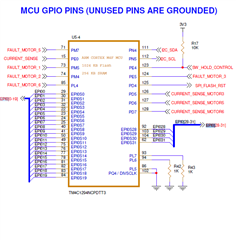
//! This example uses the following peripherals and I/O signals. You must
//! review these and change as needed for your own board:
//! - EPI0 peripheral
//! - GPIO Port A peripheral (for EPI0 pins)
//! - GPIO Port B peripheral (for EPI0 pins)
//! - GPIO Port C peripheral (for EPI0 pins)
//! - GPIO Port G peripheral (for EPI0 pins)
//! - GPIO Port K peripheral (for EPI0 pins)
//! - GPIO Port L peripheral (for EPI0 pins)
//! - GPIO Port M peripheral (for EPI0 pins)
//! - GPIO Port N peripheral (for EPI0 pins)
//! - EPI0S0 - PK0
//! - EPI0S1 - PK1
//! - EPI0S2 - PK2
//! - EPI0S3 - PK3
//! - EPI0S4 - PC7
//! - EPI0S5 - PC6
//! - EPI0S6 - PC5
//! - EPI0S7 - PC4
//! - EPI0S8 - PA6
//! - EPI0S9 - PA7
//! - EPI0S10 - PG1
//! - EPI0S11 - PG0
//! - EPI0S12 - PM3
//! - EPI0S13 - PM2
//! - EPI0S14 - PM1
//! - EPI0S15 - PM0
//! - EPI0S16 - PL0
//! - EPI0S17 - PL1
//! - EPI0S18 - PL2
//! - EPI0S19 - PL3
//! - EPI0S28 - PB3
//! - EPI0S29 - PN2
//! - EPI0S30 - PN3
//! - EPI0S31 - PK5
//!
//! The following UART signals are configured only for displaying console
//! messages for this example. These are not required for operation of EPI0.
//! - UART0 peripheral
//! - GPIO Port A peripheral (for UART0 pins)
//! - UART0RX - PA0
//! - UART0TX - PA1
//!
//! This example uses the following interrupt handlers. To use this example
//! in your own application you must add these interrupt handlers to your
//! vector table.
//! - None.
//
//*****************************************************************************
//*****************************************************************************
//
// Use the following to specify the GPIO pins used by the SDRAM EPI bus.
//
//*****************************************************************************
#define EPI_PORTA_PINS (GPIO_PIN_7 | GPIO_PIN_6)
#define EPI_PORTB_PINS (GPIO_PIN_3)
#define EPI_PORTC_PINS (GPIO_PIN_7 | GPIO_PIN_6 | GPIO_PIN_5 | GPIO_PIN_4)
#define EPI_PORTG_PINS (GPIO_PIN_1 | GPIO_PIN_0)
#define EPI_PORTK_PINS (GPIO_PIN_5 | GPIO_PIN_3 | GPIO_PIN_2 | GPIO_PIN_1 | \
GPIO_PIN_0)
#define EPI_PORTL_PINS (GPIO_PIN_3 | GPIO_PIN_2 | GPIO_PIN_1 | GPIO_PIN_0)
#define EPI_PORTM_PINS (GPIO_PIN_3 | GPIO_PIN_2 | GPIO_PIN_1 | GPIO_PIN_0)
#define EPI_PORTN_PINS (GPIO_PIN_3 | GPIO_PIN_2)
//*****************************************************************************
//
// The starting and ending address for the 64MB SDRAM chip (32Meg x 16bits) on
// the SDRAM daughter board.
//
//*****************************************************************************
#define SDRAM_START_ADDRESS 0x00000000
#define SDRAM_END_ADDRESS 0x01FFFFFF
//*****************************************************************************
//
// The Mapping address space for the EPI SDRAM.
//
//*****************************************************************************
#define SDRAM_MAPPING_ADDRESS 0x60000000
//*****************************************************************************
//
// A pointer to the EPI memory aperture. Note that g_pui16EPISdram is declared
// as volatile so the compiler should not optimize reads out of the image.
//
//*****************************************************************************
static volatile uint16_t *g_pui16EPISdram;
//*****************************************************************************
//
// A table used to determine the EPI clock frequency band in use.
//
//*****************************************************************************
typedef struct
{
uint32_t ui32SysClock;
uint32_t ui32FreqFlag;
}
tSDRAMFreqMapping;
static tSDRAMFreqMapping g_psSDRAMFreq[] =
{
//
// SysClock >= 100MHz, EPI clock >= 50Mhz (divided by 2)
//
{100000000, EPI_SDRAM_CORE_FREQ_50_100},
//
// SysClock >= 60MHz, EPI clock >= 30MHz (divided by 2)
//
{60000000, EPI_SDRAM_CORE_FREQ_50_100},
//
// SysClock >= 50MHz, EPI clock >= 50MHz (no divider)
//
{50000000, EPI_SDRAM_CORE_FREQ_50_100},
//
// SysClock >= 30MHz, EPI clock >= 30MHz (no divider)
//
{50000000, EPI_SDRAM_CORE_FREQ_30_50},
//
// SysClock >= 15MHz, EPI clock >= 15MHz (no divider)
//
{15000000, EPI_SDRAM_CORE_FREQ_15_30},
//
// SysClock < 15Mhz, EPI clock < 15Mhz (no divider)
//
{0, EPI_SDRAM_CORE_FREQ_0_15}
};
#define NUM_SDRAM_FREQ (sizeof(g_psSDRAMFreq) / sizeof(tSDRAMFreqMapping))
//*****************************************************************************
//
// This function sets up UART0 to be used for a console to display information
// as the example is running.
//
//*****************************************************************************
void
InitConsole(void)
{
//
// Enable GPIO port A which is used for UART0 pins.
// TODO: change this to whichever GPIO port you are using.
//
SysCtlPeripheralEnable(SYSCTL_PERIPH_GPIOK);
//
// Configure the pin muxing for UART0 functions on port A0 and A1.
// This step is not necessary if your part does not support pin muxing.
// TODO: change this to select the port/pin you are using.
//
GPIOPinConfigure(GPIO_PK0_U4RX);
GPIOPinConfigure(GPIO_PK1_U4TX);
//
// Enable UART0 so that we can configure the clock.
//
SysCtlPeripheralEnable(SYSCTL_PERIPH_UART4);
//
// Use the internal 16MHz oscillator as the UART clock source.
//
UARTClockSourceSet(UART4_BASE, UART_CLOCK_PIOSC);
//
// Select the alternate (UART) function for these pins.
// TODO: change this to select the port/pin you are using.
//
GPIOPinTypeUART(GPIO_PORTK_BASE, GPIO_PIN_0 | GPIO_PIN_1);
//
// Initialize the UART for console I/O.
//
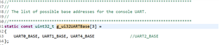
UARTStdioConfig(2, 115200, 16000000);
}
//*****************************************************************************
//
// Configure EPI0 in SDRAM mode. The EPI memory space is setup using an a
// simple C array. This example shows how to read and write to an SDRAM card
// using the EPI bus in SDRAM mode.
//
//*****************************************************************************
int
main(void)
{
uint32_t ui32Val, ui32Freq, ui32SysClock;
//
// Set the clocking to run at 120MHz from the PLL.
// TODO: Update this call to set the system clock frequency your
// application requires.
//
ui32SysClock = SysCtlClockFreqSet((SYSCTL_OSC_INT | SYSCTL_USE_PLL |
SYSCTL_CFG_VCO_320), 120000000);
//
// Set up the serial console to use for displaying messages. This is
// just for this example program and is not needed for EPI operation.
//
InitConsole();
//
// Display the setup on the console.
//
UARTprintf("EPI SDRAM Mode ->\n");
UARTprintf(" Type: SDRAM\n");
UARTprintf(" Starting Address: 0x%08x\n", SDRAM_MAPPING_ADDRESS);
UARTprintf(" End Address: 0x%08x\n",
(SDRAM_MAPPING_ADDRESS + SDRAM_END_ADDRESS));
UARTprintf(" Data: 16-bit\n");
UARTprintf(" Size: 64MB (32Meg x 16bits)\n");
//
// The EPI0 peripheral must be enabled for use.
//
SysCtlPeripheralEnable(SYSCTL_PERIPH_EPI0);
//
// For this example EPI0 is used with multiple pins on PortA, B, C, G, H,
// K, L, M and N. The actual port and pins used may be different on your
// part, consult the data sheet for more information.
// TODO: Update based upon the EPI pin assignment on your target part.
//
SysCtlPeripheralEnable(SYSCTL_PERIPH_GPIOA);
SysCtlPeripheralEnable(SYSCTL_PERIPH_GPIOB);
SysCtlPeripheralEnable(SYSCTL_PERIPH_GPIOC);
SysCtlPeripheralEnable(SYSCTL_PERIPH_GPIOG);
SysCtlPeripheralEnable(SYSCTL_PERIPH_GPIOK);
SysCtlPeripheralEnable(SYSCTL_PERIPH_GPIOL);
SysCtlPeripheralEnable(SYSCTL_PERIPH_GPIOM);
SysCtlPeripheralEnable(SYSCTL_PERIPH_GPION);
//
// This step configures the internal pin muxes to set the EPI pins for use
// with EPI. Please refer to the datasheet for more information about pin
// muxing. Note that EPI0S27:20 are not used for the EPI SDRAM
// implementation.
// TODO: Update this section based upon the EPI pin assignment on your
// target part.
//
//
// EPI0S4 ~ EPI0S7: C4 ~ 7
//
ui32Val = HWREG(GPIO_PORTC_BASE + GPIO_O_PCTL);
ui32Val &= 0x0000FFFF;
ui32Val |= 0xFFFF0000;
HWREG(GPIO_PORTC_BASE + GPIO_O_PCTL) = ui32Val;
//
// EPI0S8 ~ EPI0S9: A6 ~ 7
//
ui32Val = HWREG(GPIO_PORTA_BASE + GPIO_O_PCTL);
ui32Val &= 0x00FFFFFF;
ui32Val |= 0xFF000000;
HWREG(GPIO_PORTA_BASE + GPIO_O_PCTL) = ui32Val;
//
// EPI0S10 ~ EPI0S11: G0 ~ 1
//
ui32Val = HWREG(GPIO_PORTG_BASE + GPIO_O_PCTL);
ui32Val &= 0xFFFFFF00;
ui32Val |= 0x000000FF;
HWREG(GPIO_PORTG_BASE + GPIO_O_PCTL) = ui32Val;
//
// EPI0S12 ~ EPI0S15: M0 ~ 3
//
ui32Val = HWREG(GPIO_PORTM_BASE + GPIO_O_PCTL);
ui32Val &= 0xFFFF0000;
ui32Val |= 0x0000FFFF;
HWREG(GPIO_PORTM_BASE + GPIO_O_PCTL) = ui32Val;
//
// EPI0S16 ~ EPI0S19: L0 ~ 3
//
ui32Val = HWREG(GPIO_PORTL_BASE + GPIO_O_PCTL);
ui32Val &= 0xFFFF0000;
ui32Val |= 0x0000FFFF;
HWREG(GPIO_PORTL_BASE + GPIO_O_PCTL) = ui32Val;
//
// EPI0S28 : B3
//
ui32Val = HWREG(GPIO_PORTB_BASE + GPIO_O_PCTL);
ui32Val &= 0xFFFF0FFF;
ui32Val |= 0x0000F000;
HWREG(GPIO_PORTB_BASE + GPIO_O_PCTL) = ui32Val;
//
// EPI0S29 ~ EPI0S30: N2 ~ 3
//
ui32Val = HWREG(GPIO_PORTN_BASE + GPIO_O_PCTL);
ui32Val &= 0xFFFF00FF;
ui32Val |= 0x0000FF00;
HWREG(GPIO_PORTN_BASE + GPIO_O_PCTL) = ui32Val;
//
// EPI0S00 ~ EPI0S03, EPI0S31 : K0 ~ 3, K5
//
ui32Val = HWREG(GPIO_PORTK_BASE + GPIO_O_PCTL);
ui32Val &= 0xFF0F0000;
ui32Val |= 0x00F0FFFF;
HWREG(GPIO_PORTK_BASE + GPIO_O_PCTL) = ui32Val;
//
// Configure the GPIO pins for EPI mode. All the EPI pins require 8mA
// drive strength in push-pull operation. This step also gives control of
// pins to the EPI module.
//
GPIOPinTypeEPI(GPIO_PORTA_BASE, EPI_PORTA_PINS);
GPIOPinTypeEPI(GPIO_PORTB_BASE, EPI_PORTB_PINS);
GPIOPinTypeEPI(GPIO_PORTC_BASE, EPI_PORTC_PINS);
GPIOPinTypeEPI(GPIO_PORTG_BASE, EPI_PORTG_PINS);
GPIOPinTypeEPI(GPIO_PORTK_BASE, EPI_PORTK_PINS);
GPIOPinTypeEPI(GPIO_PORTL_BASE, EPI_PORTL_PINS);
GPIOPinTypeEPI(GPIO_PORTM_BASE, EPI_PORTM_PINS);
GPIOPinTypeEPI(GPIO_PORTN_BASE, EPI_PORTN_PINS);
//
// Is our current system clock faster than we can drive the SDRAM clock?
//
if(ui32SysClock > 60000000)
{
//
// Yes. Set the EPI clock to half the system clock.
//
EPIDividerSet(EPI0_BASE, 1);
}
else
{
//
// With a system clock of 60MHz or lower, we can drive the SDRAM at
// the same rate so set the divider to 0.
//
EPIDividerSet(EPI0_BASE, 0);
}
//
// Sets the usage mode of the EPI module. For this example we will use
// the SDRAM mode to talk to the external 64MB SDRAM daughter card.
//
EPIModeSet(EPI0_BASE, EPI_MODE_SDRAM);
//
// Keep the compiler happy by setting a default value for the frequency
// flag.
//
ui32Freq = g_psSDRAMFreq[NUM_SDRAM_FREQ - 1].ui32FreqFlag;
//
// Examine the system clock frequency to determine how to set the SDRAM
// controller's frequency flag.
//
for(ui32Val = 0; ui32Val < NUM_SDRAM_FREQ; ui32Val++)
{
//
// Is the system clock frequency above the break point in the table?
//
if(ui32SysClock >= g_psSDRAMFreq[ui32Val].ui32SysClock)
{
//
// Yes - remember the frequency flag to use and exit the loop.
//
ui32Freq = g_psSDRAMFreq[ui32Val].ui32FreqFlag;
break;
}
}
//
// Configure the SDRAM mode. We configure the SDRAM according to our core
// clock frequency. We will use the normal (or full power) operating
// state which means we will not use the low power self-refresh state.
// Set the SDRAM size to 64MB with a refresh interval of 1024 clock ticks.
//
EPIConfigSDRAMSet(EPI0_BASE, (ui32Freq | EPI_SDRAM_FULL_POWER |
EPI_SDRAM_SIZE_512MBIT), 1024);
//
// Set the address map. The EPI0 is mapped from 0x60000000 to 0x01FFFFFF.
// For this example, we will start from a base address of 0x60000000 with
// a size of 256MB. Although our SDRAM is only 64MB, there is no 64MB
// aperture option so we pick the next larger size.
//
EPIAddressMapSet(EPI0_BASE, EPI_ADDR_RAM_SIZE_256MB | EPI_ADDR_RAM_BASE_6);
//
// Wait for the SDRAM wake-up to complete by polling the SDRAM
// initialization sequence bit. This bit is true when the SDRAM interface
// is going through the initialization and false when the SDRAM interface
// it is not in a wake-up period.
//
while(HWREG(EPI0_BASE + EPI_O_STAT) & EPI_STAT_INITSEQ)
{
}
//
// Set the EPI memory pointer to the base of EPI memory space. Note that
// g_pui16EPISdram is declared as volatile so the compiler should not
// optimize reads out of the memory. With this pointer, the memory space
// is accessed like a simple array.
//
g_pui16EPISdram = (uint16_t *)0x60000000;
//
// Read the initial data in SDRAM, and display it on the console.
//
UARTprintf(" SDRAM Initial Data:\n");
UARTprintf(" Mem[0x6000.0000] = 0x%4x\n",
g_pui16EPISdram[SDRAM_START_ADDRESS]);
UARTprintf(" Mem[0x6000.0001] = 0x%4x\n",
g_pui16EPISdram[SDRAM_START_ADDRESS + 1]);
UARTprintf(" Mem[0x603F.FFFE] = 0x%4x\n",
g_pui16EPISdram[SDRAM_END_ADDRESS - 1]);
UARTprintf(" Mem[0x603F.FFFF] = 0x%4x\n\n",
g_pui16EPISdram[SDRAM_END_ADDRESS]);
//
// Display what writes we are doing on the console.
//
UARTprintf(" SDRAM Write:\n");
UARTprintf(" Mem[0x6000.0000] <- 0xabcd\n");
UARTprintf(" Mem[0x6000.0001] <- 0x1234\n");
UARTprintf(" Mem[0x603F.FFFE] <- 0xdcba\n");
UARTprintf(" Mem[0x603F.FFFF] <- 0x4321\n\n");
//
// Write to the first 2 and last 2 address of the SDRAM card. Since the
// SDRAM card is word addressable, we will write words.
//
g_pui16EPISdram[SDRAM_START_ADDRESS] = 0xabcd;
g_pui16EPISdram[SDRAM_START_ADDRESS + 1] = 0x1234;
g_pui16EPISdram[SDRAM_END_ADDRESS - 1] = 0xdcba;
g_pui16EPISdram[SDRAM_END_ADDRESS] = 0x4321;
//
// Read back the data you wrote, and display it on the console.
//
UARTprintf(" SDRAM Read:\n");
UARTprintf(" Mem[0x6000.0000] = 0x%4x\n",
g_pui16EPISdram[SDRAM_START_ADDRESS]);
UARTprintf(" Mem[0x6000.0001] = 0x%4x\n",
g_pui16EPISdram[SDRAM_START_ADDRESS + 1]);
UARTprintf(" Mem[0x603F.FFFE] = 0x%4x\n",
g_pui16EPISdram[SDRAM_END_ADDRESS - 1]);
UARTprintf(" Mem[0x603F.FFFF] = 0x%4x\n\n",
g_pui16EPISdram[SDRAM_END_ADDRESS]);
//
// Check the validity of the data.
//
if((g_pui16EPISdram[SDRAM_START_ADDRESS] == 0xabcd) &&
(g_pui16EPISdram[SDRAM_START_ADDRESS + 1] == 0x1234) &&
(g_pui16EPISdram[SDRAM_END_ADDRESS - 1] == 0xdcba) &&
(g_pui16EPISdram[SDRAM_END_ADDRESS] == 0x4321))
{
//
// Read and write operations were successful. Return with no errors.
//
UARTprintf("Read and write to external SDRAM was successful!\n");
return(0);
}
//
// Display on the console that there was an error.
//
UARTprintf("Read and/or write failure!");
UARTprintf(" Check if your SDRAM card is plugged in.");
//
// Read and/or write operations were unsuccessful. Wait in while(1) loop
// for debugging.
//
while(1)
{
}
}
Please help me to solve the issue where I stuck