Part Number: TMDSEMU110-U
Tool/software:
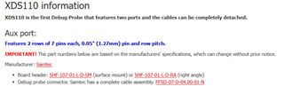
Can you provide an example mating connector for the Auxiliary Debug Interface to put on a PCB.
Also, what is the purpose of pins 1 - 4 and 6? What does it mean by Target?

Original question:

Part Number: TMDSEMU110-U
Tool/software:
Can you provide an example mating connector for the Auxiliary Debug Interface to put on a PCB.
Also, what is the purpose of pins 1 - 4 and 6? What does it mean by Target?