Part Number: TM4C1294NCPDT
Tool/software:
Hi team,
Hi Team,
I trying to up EPI0 module communicated with external SDRAM
Following is the code iam using to test in TM4C1294NCPDT
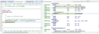
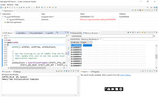
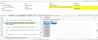
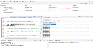
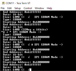
but it always reset after the prints, It is not problem with the uart , uart4 is working fine but dont know the reason why it is resetting
This is my external ram code
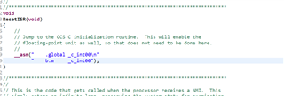
//*****************************************************************************
//
// sdram.c - Example demonstrating how to configure the EPI bus in SDRAM
// mode.
//
// Copyright (c) 2014-2020 Texas Instruments Incorporated. All rights reserved.
// Software License Agreement
//
// Redistribution and use in source and binary forms, with or without
// modification, are permitted provided that the following conditions
// are met:
//
// Redistributions of source code must retain the above copyright
// notice, this list of conditions and the following disclaimer.
//
// Redistributions in binary form must reproduce the above copyright
// notice, this list of conditions and the following disclaimer in the
// documentation and/or other materials provided with the
// distribution.
//
// Neither the name of Texas Instruments Incorporated nor the names of
// its contributors may be used to endorse or promote products derived
// from this software without specific prior written permission.
//
// THIS SOFTWARE IS PROVIDED BY THE COPYRIGHT HOLDERS AND CONTRIBUTORS
// "AS IS" AND ANY EXPRESS OR IMPLIED WARRANTIES, INCLUDING, BUT NOT
// LIMITED TO, THE IMPLIED WARRANTIES OF MERCHANTABILITY AND FITNESS FOR
// A PARTICULAR PURPOSE ARE DISCLAIMED. IN NO EVENT SHALL THE COPYRIGHT
// OWNER OR CONTRIBUTORS BE LIABLE FOR ANY DIRECT, INDIRECT, INCIDENTAL,
// SPECIAL, EXEMPLARY, OR CONSEQUENTIAL DAMAGES (INCLUDING, BUT NOT
// LIMITED TO, PROCUREMENT OF SUBSTITUTE GOODS OR SERVICES; LOSS OF USE,
// DATA, OR PROFITS; OR BUSINESS INTERRUPTION) HOWEVER CAUSED AND ON ANY
// THEORY OF LIABILITY, WHETHER IN CONTRACT, STRICT LIABILITY, OR TORT
// (INCLUDING NEGLIGENCE OR OTHERWISE) ARISING IN ANY WAY OUT OF THE USE
// OF THIS SOFTWARE, EVEN IF ADVISED OF THE POSSIBILITY OF SUCH DAMAGE.
//
// This is part of revision 2.2.0.295 of the Tiva Firmware Development Package.
//
//*****************************************************************************
#include <stdbool.h>
#include <stdint.h>
#include "inc/hw_epi.h"
#include "inc/hw_memmap.h"
#include "inc/hw_types.h"
#include "inc/hw_gpio.h"
#include "driverlib/epi.h"
#include "driverlib/gpio.h"
#include "driverlib/pin_map.h"
#include "driverlib/sysctl.h"
#include "driverlib/uart.h"
#include "utils/uartstdio.h"
//*****************************************************************************
//
//! \addtogroup epi_examples_list
//! <h1>EPI SDRAM Mode (sdram)</h1>
//!
//! This example shows how to configure the TM4C129 EPI bus in SDRAM mode. It
//! assumes that a 64Mbit SDRAM is attached to EPI0.
//!
//! For the EPI SDRAM mode, the pinout is as follows:
//! Address11:0 - EPI0S11:0
//! Bank1:0 - EPI0S14:13
//! Data15:0 - EPI0S15:0
//! DQML - EPI0S16
//! DQMH - EPI0S17
//! /CAS - EPI0S18
//! /RAS - EPI0S19
//! /WE - EPI0S28
//! /CS - EPI0S29
//! SDCKE - EPI0S30
//! SDCLK - EPI0S31
//!
//! This example uses the following peripherals and I/O signals. You must
//! review these and change as needed for your own board:
//! - EPI0 peripheral
//! - GPIO Port A peripheral (for EPI0 pins)
//! - GPIO Port B peripheral (for EPI0 pins)
//! - GPIO Port C peripheral (for EPI0 pins)
//! - GPIO Port G peripheral (for EPI0 pins)
//! - GPIO Port K peripheral (for EPI0 pins)
//! - GPIO Port L peripheral (for EPI0 pins)
//! - GPIO Port M peripheral (for EPI0 pins)
//! - GPIO Port N peripheral (for EPI0 pins)
//! - EPI0S0 - PK0
//! - EPI0S1 - PK1
//! - EPI0S2 - PK2
//! - EPI0S3 - PK3
//! - EPI0S4 - PC7
//! - EPI0S5 - PC6
//! - EPI0S6 - PC5
//! - EPI0S7 - PC4
//! - EPI0S8 - PA6
//! - EPI0S9 - PA7
//! - EPI0S10 - PG1
//! - EPI0S11 - PG0
//! - EPI0S12 - PM3
//! - EPI0S13 - PM2
//! - EPI0S14 - PM1
//! - EPI0S15 - PM0
//! - EPI0S16 - PL0
//! - EPI0S17 - PL1
//! - EPI0S18 - PL2
//! - EPI0S19 - PL3
//! - EPI0S28 - PB3
//! - EPI0S29 - PN2
//! - EPI0S30 - PN3
//! - EPI0S31 - PK5
//!
//! The following UART signals are configured only for displaying console
//! messages for this example. These are not required for operation of EPI0.
//! - UART0 peripheral
//! - GPIO Port A peripheral (for UART0 pins)
//! - UART0RX - PA0
//! - UART0TX - PA1
//!
//! This example uses the following interrupt handlers. To use this example
//! in your own application you must add these interrupt handlers to your
//! vector table.
//! - None.
//
//*****************************************************************************
//*****************************************************************************
//
// Use the following to specify the GPIO pins used by the SDRAM EPI bus.
//
//*****************************************************************************
#define EPI_PORTA_PINS (GPIO_PIN_7 | GPIO_PIN_6)
#define EPI_PORTB_PINS (GPIO_PIN_3)
#define EPI_PORTC_PINS (GPIO_PIN_7 | GPIO_PIN_6 | GPIO_PIN_5 | GPIO_PIN_4)
#define EPI_PORTG_PINS (GPIO_PIN_1 | GPIO_PIN_0)
#define EPI_PORTK_PINS (GPIO_PIN_5 | GPIO_PIN_3 | GPIO_PIN_2 | GPIO_PIN_1 | \
GPIO_PIN_0)
#define EPI_PORTL_PINS (GPIO_PIN_3 | GPIO_PIN_2 | GPIO_PIN_1 | GPIO_PIN_0)
#define EPI_PORTM_PINS (GPIO_PIN_3 | GPIO_PIN_2 | GPIO_PIN_1 | GPIO_PIN_0)
#define EPI_PORTN_PINS (GPIO_PIN_3 | GPIO_PIN_2)
//*****************************************************************************
//
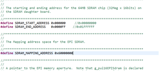
// The starting and ending address for the 64MB SDRAM chip (32Meg x 16bits) on
// the SDRAM daughter board.
//
//*****************************************************************************
#define SDRAM_START_ADDRESS 0x00000000
#define SDRAM_END_ADDRESS 0x01FFFFFF
//*****************************************************************************
//
// The Mapping address space for the EPI SDRAM.
//
//*****************************************************************************
#define SDRAM_MAPPING_ADDRESS 0x60000000
//*****************************************************************************
//
// A pointer to the EPI memory aperture. Note that g_pui16EPISdram is declared
// as volatile so the compiler should not optimize reads out of the image.
//
//*****************************************************************************
static volatile uint16_t *g_pui16EPISdram;
//*****************************************************************************
//
// A table used to determine the EPI clock frequency band in use.
//
//*****************************************************************************
typedef struct
{
uint32_t ui32SysClock;
uint32_t ui32FreqFlag;
}
tSDRAMFreqMapping;
static tSDRAMFreqMapping g_psSDRAMFreq[] =
{
//
// SysClock >= 100MHz, EPI clock >= 50Mhz (divided by 2)
//
{100000000, EPI_SDRAM_CORE_FREQ_50_100},
//
// SysClock >= 60MHz, EPI clock >= 30MHz (divided by 2)
//
{60000000, EPI_SDRAM_CORE_FREQ_50_100},
//
// SysClock >= 50MHz, EPI clock >= 50MHz (no divider)
//
{50000000, EPI_SDRAM_CORE_FREQ_50_100},
//
// SysClock >= 30MHz, EPI clock >= 30MHz (no divider)
//
{50000000, EPI_SDRAM_CORE_FREQ_30_50},
//
// SysClock >= 15MHz, EPI clock >= 15MHz (no divider)
//
{15000000, EPI_SDRAM_CORE_FREQ_15_30},
//
// SysClock < 15Mhz, EPI clock < 15Mhz (no divider)
//
{0, EPI_SDRAM_CORE_FREQ_0_15}
};
#define NUM_SDRAM_FREQ (sizeof(g_psSDRAMFreq) / sizeof(tSDRAMFreqMapping))
//*****************************************************************************
//
// This function sets up UART0 to be used for a console to display information
// as the example is running.
//
//*****************************************************************************
void
InitConsole(void)
{
//
// Enable GPIO port A which is used for UART0 pins.
// TODO: change this to whichever GPIO port you are using.
//
SysCtlPeripheralEnable(SYSCTL_PERIPH_GPIOK);
//
// Configure the pin muxing for UART0 functions on port A0 and A1.
// This step is not necessary if your part does not support pin muxing.
// TODO: change this to select the port/pin you are using.
//
GPIOPinConfigure(GPIO_PK0_U4RX);
GPIOPinConfigure(GPIO_PK1_U4TX);
//
// Enable UART0 so that we can configure the clock.
//
SysCtlPeripheralEnable(SYSCTL_PERIPH_UART4);
//
// Use the internal 16MHz oscillator as the UART clock source.
//
UARTClockSourceSet(UART4_BASE, UART_CLOCK_PIOSC);
//
// Select the alternate (UART) function for these pins.
// TODO: change this to select the port/pin you are using.
//
GPIOPinTypeUART(GPIO_PORTK_BASE, GPIO_PIN_0 | GPIO_PIN_1);
//
// Initialize the UART for console I/O.
//
UARTStdioConfig(2, 115200, 16000000);
}
//*****************************************************************************
//
// Configure EPI0 in SDRAM mode. The EPI memory space is setup using an a
// simple C array. This example shows how to read and write to an SDRAM card
// using the EPI bus in SDRAM mode.
//
//*****************************************************************************
int
main(void)
{
uint32_t ui32Val, ui32Freq, ui32SysClock;
//
// Set the clocking to run at 120MHz from the PLL.
// TODO: Update this call to set the system clock frequency your
// application requires.
//
ui32SysClock = SysCtlClockFreqSet((SYSCTL_OSC_INT | SYSCTL_USE_PLL |
SYSCTL_CFG_VCO_320), 120000000);
//
// Set up the serial console to use for displaying messages. This is
// just for this example program and is not needed for EPI operation.
//
InitConsole();
//
// Display the setup on the console.
//
UARTprintf("EPI SDRAM Mode ->\n");
UARTprintf(" Type: SDRAM\n");
UARTprintf(" Starting Address: 0x%08x\n", SDRAM_MAPPING_ADDRESS);
UARTprintf(" End Address: 0x%08x\n",
(SDRAM_MAPPING_ADDRESS + SDRAM_END_ADDRESS));
UARTprintf(" Data: 16-bit\n");
UARTprintf(" Size: 64MB (32Meg x 16bits)\n");
//
// The EPI0 peripheral must be enabled for use.
//
SysCtlPeripheralEnable(SYSCTL_PERIPH_EPI0);
//
// For this example EPI0 is used with multiple pins on PortA, B, C, G, H,
// K, L, M and N. The actual port and pins used may be different on your
// part, consult the data sheet for more information.
// TODO: Update based upon the EPI pin assignment on your target part.
//
SysCtlPeripheralEnable(SYSCTL_PERIPH_GPIOA);
SysCtlPeripheralEnable(SYSCTL_PERIPH_GPIOB);
SysCtlPeripheralEnable(SYSCTL_PERIPH_GPIOC);
SysCtlPeripheralEnable(SYSCTL_PERIPH_GPIOG);
SysCtlPeripheralEnable(SYSCTL_PERIPH_GPIOK);
SysCtlPeripheralEnable(SYSCTL_PERIPH_GPIOL);
SysCtlPeripheralEnable(SYSCTL_PERIPH_GPIOM);
SysCtlPeripheralEnable(SYSCTL_PERIPH_GPION);
//
// This step configures the internal pin muxes to set the EPI pins for use
// with EPI. Please refer to the datasheet for more information about pin
// muxing. Note that EPI0S27:20 are not used for the EPI SDRAM
// implementation.
// TODO: Update this section based upon the EPI pin assignment on your
// target part.
//
//
// EPI0S4 ~ EPI0S7: C4 ~ 7
//
ui32Val = HWREG(GPIO_PORTC_BASE + GPIO_O_PCTL);
ui32Val &= 0x0000FFFF;
ui32Val |= 0xFFFF0000;
HWREG(GPIO_PORTC_BASE + GPIO_O_PCTL) = ui32Val;
//
// EPI0S8 ~ EPI0S9: A6 ~ 7
//
ui32Val = HWREG(GPIO_PORTA_BASE + GPIO_O_PCTL);
ui32Val &= 0x00FFFFFF;
ui32Val |= 0xFF000000;
HWREG(GPIO_PORTA_BASE + GPIO_O_PCTL) = ui32Val;
//
// EPI0S10 ~ EPI0S11: G0 ~ 1
//
ui32Val = HWREG(GPIO_PORTG_BASE + GPIO_O_PCTL);
ui32Val &= 0xFFFFFF00;
ui32Val |= 0x000000FF;
HWREG(GPIO_PORTG_BASE + GPIO_O_PCTL) = ui32Val;
//
// EPI0S12 ~ EPI0S15: M0 ~ 3
//
ui32Val = HWREG(GPIO_PORTM_BASE + GPIO_O_PCTL);
ui32Val &= 0xFFFF0000;
ui32Val |= 0x0000FFFF;
HWREG(GPIO_PORTM_BASE + GPIO_O_PCTL) = ui32Val;
//
// EPI0S16 ~ EPI0S19: L0 ~ 3
//
ui32Val = HWREG(GPIO_PORTL_BASE + GPIO_O_PCTL);
ui32Val &= 0xFFFF0000;
ui32Val |= 0x0000FFFF;
HWREG(GPIO_PORTL_BASE + GPIO_O_PCTL) = ui32Val;
//
// EPI0S28 : B3
//
ui32Val = HWREG(GPIO_PORTB_BASE + GPIO_O_PCTL);
ui32Val &= 0xFFFF0FFF;
ui32Val |= 0x0000F000;
HWREG(GPIO_PORTB_BASE + GPIO_O_PCTL) = ui32Val;
//
// EPI0S29 ~ EPI0S30: N2 ~ 3
//
ui32Val = HWREG(GPIO_PORTN_BASE + GPIO_O_PCTL);
ui32Val &= 0xFFFF00FF;
ui32Val |= 0x0000FF00;
HWREG(GPIO_PORTN_BASE + GPIO_O_PCTL) = ui32Val;
//
// EPI0S00 ~ EPI0S03, EPI0S31 : K0 ~ 3, K5
//
ui32Val = HWREG(GPIO_PORTK_BASE + GPIO_O_PCTL);
ui32Val &= 0xFF0F0000;
ui32Val |= 0x00F0FFFF;
HWREG(GPIO_PORTK_BASE + GPIO_O_PCTL) = ui32Val;
//
// Configure the GPIO pins for EPI mode. All the EPI pins require 8mA
// drive strength in push-pull operation. This step also gives control of
// pins to the EPI module.
//
GPIOPinTypeEPI(GPIO_PORTA_BASE, EPI_PORTA_PINS);
GPIOPinTypeEPI(GPIO_PORTB_BASE, EPI_PORTB_PINS);
GPIOPinTypeEPI(GPIO_PORTC_BASE, EPI_PORTC_PINS);
GPIOPinTypeEPI(GPIO_PORTG_BASE, EPI_PORTG_PINS);
GPIOPinTypeEPI(GPIO_PORTK_BASE, EPI_PORTK_PINS);
GPIOPinTypeEPI(GPIO_PORTL_BASE, EPI_PORTL_PINS);
GPIOPinTypeEPI(GPIO_PORTM_BASE, EPI_PORTM_PINS);
GPIOPinTypeEPI(GPIO_PORTN_BASE, EPI_PORTN_PINS);
//
// Is our current system clock faster than we can drive the SDRAM clock?
//
if(ui32SysClock > 60000000)
{
//
// Yes. Set the EPI clock to half the system clock.
//
EPIDividerSet(EPI0_BASE, 1);
}
else
{
//
// With a system clock of 60MHz or lower, we can drive the SDRAM at
// the same rate so set the divider to 0.
//
EPIDividerSet(EPI0_BASE, 0);
}
//
// Sets the usage mode of the EPI module. For this example we will use
// the SDRAM mode to talk to the external 64MB SDRAM daughter card.
//
EPIModeSet(EPI0_BASE, EPI_MODE_SDRAM);
//
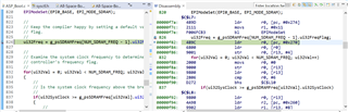
// Keep the compiler happy by setting a default value for the frequency
// flag.
//
ui32Freq = g_psSDRAMFreq[NUM_SDRAM_FREQ - 1].ui32FreqFlag;
//
// Examine the system clock frequency to determine how to set the SDRAM
// controller's frequency flag.
//
for(ui32Val = 0; ui32Val < NUM_SDRAM_FREQ; ui32Val++)
{
//
// Is the system clock frequency above the break point in the table?
//
if(ui32SysClock >= g_psSDRAMFreq[ui32Val].ui32SysClock)
{
//
// Yes - remember the frequency flag to use and exit the loop.
//
ui32Freq = g_psSDRAMFreq[ui32Val].ui32FreqFlag;
break;
}
}
//
// Configure the SDRAM mode. We configure the SDRAM according to our core
// clock frequency. We will use the normal (or full power) operating
// state which means we will not use the low power self-refresh state.
// Set the SDRAM size to 64MB with a refresh interval of 1024 clock ticks.
//
EPIConfigSDRAMSet(EPI0_BASE, (ui32Freq | EPI_SDRAM_FULL_POWER |
EPI_SDRAM_SIZE_512MBIT), 1024);
//
// Set the address map. The EPI0 is mapped from 0x60000000 to 0x01FFFFFF.
// For this example, we will start from a base address of 0x60000000 with
// a size of 256MB. Although our SDRAM is only 64MB, there is no 64MB
// aperture option so we pick the next larger size.
//
EPIAddressMapSet(EPI0_BASE, EPI_ADDR_RAM_SIZE_256MB | EPI_ADDR_RAM_BASE_6);
//
// Wait for the SDRAM wake-up to complete by polling the SDRAM
// initialization sequence bit. This bit is true when the SDRAM interface
// is going through the initialization and false when the SDRAM interface
// it is not in a wake-up period.
//
while(HWREG(EPI0_BASE + EPI_O_STAT) & EPI_STAT_INITSEQ)
{
}
//
// Set the EPI memory pointer to the base of EPI memory space. Note that
// g_pui16EPISdram is declared as volatile so the compiler should not
// optimize reads out of the memory. With this pointer, the memory space
// is accessed like a simple array.
//
g_pui16EPISdram = (uint16_t *)0x60000000;
//
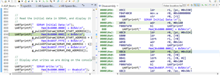
// Read the initial data in SDRAM, and display it on the console.
//
UARTprintf(" SDRAM Initial Data:\n");
UARTprintf(" Mem[0x6000.0000] = 0x%4x\n",
g_pui16EPISdram[SDRAM_START_ADDRESS]);
UARTprintf(" Mem[0x6000.0001] = 0x%4x\n",
g_pui16EPISdram[SDRAM_START_ADDRESS + 1]);
UARTprintf(" Mem[0x603F.FFFE] = 0x%4x\n",
g_pui16EPISdram[SDRAM_END_ADDRESS - 1]);
UARTprintf(" Mem[0x603F.FFFF] = 0x%4x\n\n",
g_pui16EPISdram[SDRAM_END_ADDRESS]);
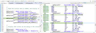
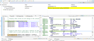
//
// Display what writes we are doing on the console.
//
UARTprintf(" SDRAM Write:\n");
UARTprintf(" Mem[0x6000.0000] <- 0xabcd\n");
UARTprintf(" Mem[0x6000.0001] <- 0x1234\n");
UARTprintf(" Mem[0x603F.FFFE] <- 0xdcba\n");
UARTprintf(" Mem[0x603F.FFFF] <- 0x4321\n\n");
//
// Write to the first 2 and last 2 address of the SDRAM card. Since the
// SDRAM card is word addressable, we will write words.
//
g_pui16EPISdram[SDRAM_START_ADDRESS] = 0xabcd;
g_pui16EPISdram[SDRAM_START_ADDRESS + 1] = 0x1234;
g_pui16EPISdram[SDRAM_END_ADDRESS - 1] = 0xdcba;
g_pui16EPISdram[SDRAM_END_ADDRESS] = 0x4321;
//
// Read back the data you wrote, and display it on the console.
//
UARTprintf(" SDRAM Read:\n");
UARTprintf(" Mem[0x6000.0000] = 0x%4x\n",
g_pui16EPISdram[SDRAM_START_ADDRESS]);
UARTprintf(" Mem[0x6000.0001] = 0x%4x\n",
g_pui16EPISdram[SDRAM_START_ADDRESS + 1]);
UARTprintf(" Mem[0x603F.FFFE] = 0x%4x\n",
g_pui16EPISdram[SDRAM_END_ADDRESS - 1]);
UARTprintf(" Mem[0x603F.FFFF] = 0x%4x\n\n",
g_pui16EPISdram[SDRAM_END_ADDRESS]);
//
// Check the validity of the data.
//
if((g_pui16EPISdram[SDRAM_START_ADDRESS] == 0xabcd) &&
(g_pui16EPISdram[SDRAM_START_ADDRESS + 1] == 0x1234) &&
(g_pui16EPISdram[SDRAM_END_ADDRESS - 1] == 0xdcba) &&
(g_pui16EPISdram[SDRAM_END_ADDRESS] == 0x4321))
{
//
// Read and write operations were successful. Return with no errors.
//
UARTprintf("Read and write to external SDRAM was successful!\n");
return(0);
}
//
// Display on the console that there was an error.
//
UARTprintf("Read and/or write failure!");
UARTprintf(" Check if your SDRAM card is plugged in.");
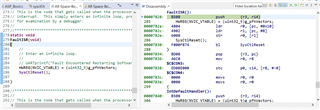
//
// Read and/or write operations were unsuccessful. Wait in while(1) loop
// for debugging.
//
while(1)
{
}
}
my .cmd linker file
/******************************************************************************
 *
 * Medtronic-HHC-primary.cmd - CCS linker configuration file for medtronic primary.
 *
 * Copyright (c) 2013-2017 Texas Instruments Incorporated.  All rights reserved.
 * Software License Agreement
 *
 * Texas Instruments (TI) is supplying this software for use solely and
 * exclusively on TI's microcontroller products. The software is owned by
 * TI and/or its suppliers, and is protected under applicable copyright
 * laws. You may not combine this software with "viral" open-source
 * software in order to form a larger program.
 *
 * THIS SOFTWARE IS PROVIDED "AS IS" AND WITH ALL FAULTS.
 * NO WARRANTIES, WHETHER EXPRESS, IMPLIED OR STATUTORY, INCLUDING, BUT
 * NOT LIMITED TO, IMPLIED WARRANTIES OF MERCHANTABILITY AND FITNESS FOR
 * A PARTICULAR PURPOSE APPLY TO THIS SOFTWARE. TI SHALL NOT, UNDER ANY
 * CIRCUMSTANCES, BE LIABLE FOR SPECIAL, INCIDENTAL, OR CONSEQUENTIAL
 * DAMAGES, FOR ANY REASON WHATSOEVER.
 *
 *
 *****************************************************************************/

--retain=g_pfnVectors

/* The following command line options are set as part of the CCS project.    */
/* If you are building using the command line, or for some reason want to    */
/* define them here, you can uncomment and modify these lines as needed.     */
/* If you are using CCS for building, it is probably better to make any such */
/* modifications in your CCS project and leave this file alone.              */
/*                                                                           */
/* --heap_size=0                                                             */
/* --stack_size=256                                                          */
/* --library=rtsv7M3_T_le_eabi.lib                                           */

/* The starting address of the application.  Normally the interrupt vectors  */
/* must be located at the beginning of the application.                      */
#define APP_BASE	0x00000000
#define RAM_BASE	0x20000000
#define APP_LENGTH	0x00016000

/* System memory map */

MEMORY
{
   /* Application stored in and executes from internal flash */
    FLASH (RX) : origin = APP_BASE, length = APP_LENGTH
    /* Application uses internal RAM for data */
    SRAM (RWX) : origin = RAM_BASE, length = 0x00040000
}

/* Section allocation in memory */

SECTIONS
{
    .intvecs:   > APP_BASE
    .text   :   > FLASH
    .const  :   > FLASH
    .cinit  :   > FLASH
    .pinit  :   > FLASH
    .init_array : > FLASH

    .vtable :   > RAM_BASE
    .data   :   > SRAM
    .bss    :   > SRAM
    .sysmem :   > SRAM
    .stack  :   > SRAM

#ifdef  __TI_COMPILER_VERSION__
#if     __TI_COMPILER_VERSION__ >= 15009000
    .TI.ramfunc : {} load=FLASH, run=SRAM, table(BINIT)
#endif
#endif
}
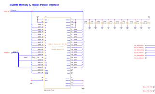
hardware connection diagram
This is the external RAM part number
IS45S16100H-7TLA2
...
can you please help me to solve the issue