This thread has been locked.

If you have a related question, please click the "Ask a related question" button in the top right corner. The newly created question will be automatically linked to this question.

MSPM0C1104: about I2C clock is pulled low

Part Number: MSPM0C1104
Other Parts Discussed in Thread: UNIFLASH,

Tool/software:

Hi team,

Customer use i2ctest to query MCU (they configure MCU to an i2c target with it's address 0x48)  but found there is no response  from MCU and they used scope to check the i2c's waveform and found SCL will become low after few clock cycles as attachment.  This issue is always happened


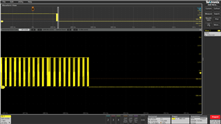
Customer use SDK: mspm0_sdk_2_03_00_07


Questions:

Customer use M0C1104 WSON.  They worry about the I2C clock and the NRST use the same pin. The I2C clock is pulled by peer device (not M0C104). Sometimes, the peer device might lost power suddenly. They worry when I2C clock is low suddenly. This will trigger NRST to M0C1104.

They also have below two questions. Please help clarify. Thank you.

  1. For the download firmware to MSPM0C1104SDSGR by SWD, do we need NRST pin, or we only need VDD, VSS, SWCLK and SWDIO?
  2. For the I2C and NREST share same pin at MSPM0C1104SDSGR, when will trigger the reset function? Will it trigger reset during I2C transmission.


  • Hi, 

    For the download firmware to MSPM0C1104SDSGR by SWD, do we need NRST pin, or we only need VDD, VSS, SWCLK and SWDIO?

    At least 3pin: SWDIO, SWCLK and GND.

    Power supply VDD need to be connected to M0 if there is no other supply.

    NRST is for further debug use, such as factory reset action.

    I recommend to add some NRST testpoint in development phase for easier debug.

    For the I2C and NREST share same pin at MSPM0C1104SDSGR, when will trigger the reset function? Will it trigger reset during I2C transmission.

    I2C pin with NRST, NRST function need to be disabled during init, you can disable it in syscfg or at the first line in main.

    I recommend you add some delay before disable I2C in init, because in development phase, need to reserve NRST function at boot in case such as Factory Reset is needed.

    Step:

    main{

    delay_cycles(24000000*5); delay 5s

    Disable NRST;

    Syscfg init;

    User function.....

    }

    Also, NRST disable configuration can be only reset after POR, power on reset.

    Regards,

    Helic

  • Hi Helic,

    I recommend you add some delay before disable I2C in init

    Is this wording typo ?  Do you mean add some delay before disable NRST in init ?

  • Yes, add some delay to make sure if need NRST function, there are some seconds after boot you can do some Factory reset.

  • Hi  

    For the MSPM0C1104SDSGR, we find it will show warring message, if we don't disable NRST function before set I2C for pin2  in syscfg, 

    As your suggestion that disable NRST after few second POR, does that mean we still need disable NRST function in syscfg and added delay time for disable NRST in main.

  • Hi, 

    Both disable in main and syscfg will work normally.

    In development phase:

    What I want you to do is to disable NRST in main with some delay, this will keep some time windows for debug use.

    And in production phase, 

    You can directly disable NRST in syscfg.

    If you want just disable NRST in syscfg, it's OK.

    Regards,

    Helic

  • Hi 

    Thank you for the reply.

    Currently we are using uniflash to download firmware to MCU, that is a UI interface.

      Is there a way to download firmware by command line interface that can download firmware by script

  • hi 

    Recently, the factory encountered an issue where dozens of MSPM0C1104SDSGR MCUs failed to download firmware. Previously, we had successfully downloaded firmware to hundreds of MCUs without any abnormalities.

    Our initial swap test, exchanging MCUs between working and non-working boards, confirmed that the issue follows the MCU itself. Additionally, we found that two of these MCUs could eventually recover if repeatedly flashed without power cycling.

    we got the message from syscfg when the MCU recover to normal
    =========================================================================

    [2/28/2025, 8:28:17 PM] [ERROR] CORTEX_M0P: Error connecting to the target: Could not connect to target.
    [2/28/2025, 8:28:19 PM] [INFO] CORTEX_M0P: GEL Output: Memory Map Initialization Complete
    [2/28/2025, 8:28:20 PM] [ERROR] CORTEX_M0P: Trouble Writing Register PC: PC of target system has unexpected value after erasing sectors. (PC = 0x00000000)! ---------------------------------------------------------------------- Registers ------------------------------------------------------------------------------------- PC = 00000000 Current: R0 = 00000000, R1 = 00000000, R2 = 00000000, R3 = 00000000 R4 = 00000000, R5 = 00000000, R6 = 00000000, R7 = 00000000 ---------------------------------------------------------------------------------------------------------------------------------------------------------------------------- Failed to erase sectors. Cannot read register 20 (CFBP) while CPU is runningCPU is not haltedCannot read register 15 (R15) while CPU is runningCannot read register 7 (R7) while CPU is runningCannot read register 6 (R6) while CPU is runningCannot read register 5 (R5) while CPU is runningCannot read register 4 (R4) while CPU is runningCannot read register 3 (R3) while CPU is runningCannot read register 2 (R2) while CPU is runnin
    [2/28/2025, 8:28:20 PM] [SUCCESS] Program Load completed successfully.

    ===================================================================================

    we got the message from syscfg when the another MCU recover to normal

    ===========================================================================================

    [2/28/2025, 7:30:38 PM] [ERROR] CORTEX_M0P: Error connecting to the target: Could not connect to target.
    [2/28/2025, 7:30:41 PM] [ERROR] CORTEX_M0P: Error connecting to the target: Could not connect to target.
    [2/28/2025, 7:30:43 PM] [INFO] CORTEX_M0P: GEL Output: Memory Map Initialization Complete
    [2/28/2025, 7:30:44 PM] [ERROR] CORTEX_M0P: Trouble Writing Register PC: PC of target system has unexpected value after erasing sectors. (PC = 0xFFFFFFFF)! ---------------------------------------------------------------------- Registers ------------------------------------------------------------------------------------- PC = FFFFFFFF Current: R0 = 00000000, R1 = 80000000, R2 = 00000000, R3 = FFFFFFFF R4 = FFFFFFFF, R5 = FFFFFFFF, R6 = 00000000, R7 = FFFFFFFF ---------------------------------------------------------------------------------------------------------------------------------------------------------------------------- Failed to erase sectors.
    [2/28/2025, 7:30:44 PM] [SUCCESS] Program Load completed successfully.
    [2/28/2025, 7:32:57 PM] [INFO] CORTEX_M0P: GEL Output: Memory Map Initialization Complete
    [2/28/2025, 7:32:58 PM] [SUCCESS] Program Load completed successfully.
    [2/28/2025, 7:33:04 PM] [INFO] CORTEX_M0P: GEL Output: Memory Map Initialization Complete

    ============================================================================================

    We suspect that the MCU might be locked, or the message has showing those MCU has potential  issue

    1. What could cause the MCU to lock?
    2. What methods are available to unlock the MCU?

     
  • hi 

    Thanks for your answer. But  my "setting & utilities" page is blank, that don't have any buttom and selector like the link you show to me.

    Is there has any thing I missed

    I am useing the UniFlash, MSPM0C1104, SEGGER J-Link Emulator.

  • Hi, 

    Factory reset requires XDS110 debug probe, you are using Jlink.

    Regards,

    Helic