This thread has been locked.

If you have a related question, please click the "Ask a related question" button in the top right corner. The newly created question will be automatically linked to this question.

TM4C129ENCZAD: General Purpose Timers to measure PWM duty cycle

Part Number: TM4C129ENCZAD

Tool/software:

Hello,
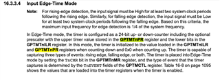
I am trying to measure the PWM duty cycle using the General Purpose Timer Module's Capture Compare Mode in Edge Timer Configuration. The frequency of the signal measured is 482 Hz.  Below is the code I used for initialization of the pins. 

```SysCtlPeripheralEnable(SYSCTL_PERIPH_TIMER2);
TimerConfigure(TIMER2_BASE,
(TIMER_CFG_SPLIT_PAIR | TIMER_CFG_A_CAP_TIME_UP | TIMER_CFG_B_CAP_TIME_UP));
TimerControlEvent(TIMER2_BASE, TIMER_A, TIMER_EVENT_POS_EDGE);
TimerControlEvent(TIMER2_BASE, TIMER_B, TIMER_EVENT_NEG_EDGE);
TimerEnable(TIMER2_BASE, TIMER_A);
TimerEnable(TIMER2_BASE, TIMER_B);```

The init functions above are all part of tivaware library. I think the initialization worked fine as I am able to get some timer values on providing a PWM signal on the pin. 

Below is the code I am using for recording the total PWM pulse.

```void SpinMotorImpl::MeasureSpinSpeed() {
static uint16_t counter = 0;
static bool previous_measured = false;
static uint32_t spin_mot_hlfb_rising_prev=0;
uint32_t status_pos = TimerIntStatus(TIMER2_BASE, false);
if ((status_pos & TIMER_CAPA_EVENT ) != 0) {
const uint32_t spin_mot_hlfb_rising = (TimerValueGet(TIMER2_BASE, TIMER_A)&0x00FFFFFF);
const uint32_t spin_mot_hlfb_falling = (TimerValueGet(TIMER2_BASE, TIMER_B)&0x00FFFFFF);
if(!previous_measured)
{
spin_mot_hlfb_rising_prev = spin_mot_hlfb_rising;
previous_measured=true;
}
else
{
counter++;
if(counter==1000)
{
syslog_->Printf(SYSLOG_LEVEL_INFO, "m_evt=MeasureSpinSpeed timings=%ld, %ld, %ld", spin_mot_hlfb_rising, spin_mot_hlfb_rising_prev, spin_mot_hlfb_falling);
counter=0;
}
previous_measured = false;
TimerReset(TIMER2_BASE, TIMER_BOTH);
}
TimerIntClear(TIMER2_BASE, TIMER_CAPA_EVENT);
TimerIntClear(TIMER2_BASE, TIMER_CAPB_EVENT);
}
}```

The MeasureSpinSpeed is called every 1 ms. I cannot print at every cycle because that crashes the micro, I am guessing because it overloads it, which is why I have a counter that counts upto 1000 and I print every sec that way. 
Based on this code, I expected to see the spin_mot_hlfb_rising to be higher than the spin_mot_hlfb_rising_prev and the spin_mot_hlfb_falling to be somewhere in between ( there should be a falling edge between two rising edges.)

However, this is what I am seeing:

m_evt=MeasureSpinSpeed timings=27640, 40830, 43379 ca

Based on this log message: spin_mot_hlfb_rising_prev is 40830, spin_mot_hlfb_falling = 43379 and spin_mot_hlfb_rising = 27640. The values differ every log message but the difference between these values is consistent.

I have two questions:

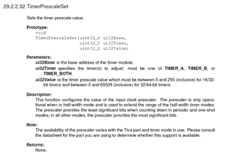
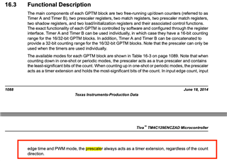
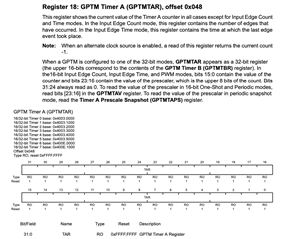
1. The timer seems to be wrapping around 65536. I cannot figure out how to prescale this. The datasheet says that in Edge Timer mode, the prescale byte just acts like an extra 8 bits to the 16 bit signal. I am guessing this makes it a 24 bit signal, which is why I am using a 0x00FFFFFF to extract out 24 bits but it still seems to wrap around 65536.

2. Why is the current timer value for the rising edge always lower than the prev rising edge and the falling edge is always higher than both of them. Tapping the signal at 1 kHz for a 482 Hz signal should be fine I think. The falling edge should be in between them, unless it is the wrapping around somewhere in between in which case figuring out how to prescale would really help here. 

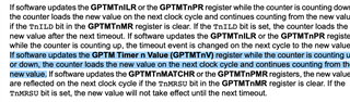
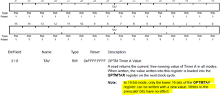
FYI: TimerReset resets the GPTMTAV and GPTMTBV registers of the timer to 0,TimerIntClear sets the GPTMICR flag for clearing the GPTMRIS flag of the timer, TimerValueGet gets the values in GPTMTnR registers and TimerIntStatus gets the values of the GPTMRIS registers to check if there has been an edge. 

Not sure if I clarified my question above but would love to answer any questions you would have about my question.
Thank you in advance for your help.

  • Hi,

     I think the first thing you must not do is to use printf in your code. printf takes a tremendous amount of time to send through the CIO which impact real time operation. You should send your message out using UARTprintf which will send the message to the UART port. 

     Are you measuring the duty cycle or the period of the input. It seems you are trying to measure the duty with your input period equal to1kHz. Please clarify what you want to measure. If you are measuring duty then it will vary, isn't? If you are measuring period then why are you using one timer for pos edge and the other for neg edge? A period measurement should be from either pos to pos edge or neg to neg edge. 

    You need to use TimerPrescalerSet to configure the presacler. 

  • I am actually trying to measure the duty cycle of the signal. I am trying to measure it by dividing the pos-neg edge time difference and pos-pos edge time difference. The pos - pos_prev should give me total and (neg - pos_prev)/(pos-pos_prev) should give me duty cycle. However, it does not line up with data I am seeing for those times. The neg edge time is always higher than all three and pos_prev is higher than pos. I dont understand how that is possible. 

    Regarding prescaler, reading through the documentation:


    From what I understand, in edge time mode, the prescaler byte is an extension of the 16 bit timer, making it a 24 bit timer, since it holds the most significant bytes of the count. By that logic, I need to extract 24 bits or 0x00FFFFFF like I have done in the code. Correct me if I am wrong in my understanding.

  • I just tried TimerPrescaleSet to 4, and I still see the same values and the same difference between the values so it didnt really prescale anything. Then I tried checking the prescale register during the operation to see if it holds the 8 most significant bits of the count and it doesnt do that either and always reports 0. It is neither acting as an extension or an actual prescaler. Not sure what is going on here.

  • Hi,

    I am actually trying to measure the duty cycle of the signal. I am trying to measure it by dividing the pos-neg edge time difference and pos-pos edge time difference.

    Thanks for the clarification. 

    From what I understand, in edge time mode, the prescaler byte is an extension of the 16 bit timer, making it a 24 bit timer, since it holds the most significant bytes of the count. By that logic, I need to extract 24 bits or 0x00FFFFFF like I have done in the code. Correct me if I am wrong in my understanding.

     Can you try the below. 

    TimerPrescaleSet(TIMER0_BASE, TIMER_A, 0xFF);
    TimerLoadSet(TIMER0_BASE, TIMER_A, 0xFFFF);

    This will create a full 24-bit timer since the preload value would be 0xFF_FFFF. The free running counter will count from 0 to 0xFF_FFFF before it resets to zero again. The 24-bit counter gives a maximum 139.25ms at 120MHz.

  • That got the timer extended. Thank you. And I think it did also solve the problem because the root cause was prescaler the whole time. I still am confused though because I went over the document so many times and I couldn't figure this trick out. Was this written in the documentation somewhere that I missed?

  • Hi,

      The preload value defines the upper limit beyond which the counter will reset when counting up to from 0. By setting the preload value to FF_FFFF this gives the counter a maximum of 24 bits to count up to. When counting down, the preload value defines the starting value for the counter. After the counter reaches zero, it is reloaded with the programmed preload value again. I understand the d/s is not very clear on the input capture time mode for counting up. 

  • Hello,
    Thank you for helping me so far.

    I am still facing a problem with timer reset in the TimerEdgeTime mode. This is what my timer reset function looks like:

    void
    TimerReset(uint32_t ui32Base, uint32_t ui32Timer)
    {
    if((ui32Timer & TIMER_A) == TIMER_A)
    {
    HWREG(ui32Base + TIMER_O_TAV) = 0x00FFFFFF;
    }
    if((ui32Timer & TIMER_B) == TIMER_B)
    {
    HWREG(ui32Base + TIMER_O_TBV) = 0x00FFFFFF;
    }
    }

    This however does not reset the timer to 0. Not sure why?
    This is the documentation I am referring to 

    It clearly says I need to write to the TnV registers, but it does not work. I also tried:

    TimerDisable(TIMER2_BASE, TIMER_BOTH);
    TimerPrescaleSet(TIMER2_BASE, TIMER_BOTH, 0xFF);
    TimerLoadSet(TIMER2_BASE, TIMER_BOTH, 0xFFFF);
    TimerEnable(TIMER2_BASE, TIMER_BOTH);

    but that does not reset the timer also. It would be great if I could get help on this. If I need to create a separate post let me know.

  • I am still facing a problem with timer reset in the TimerEdgeTime mode. This is what my timer reset function looks like:

    void
    TimerReset(uint32_t ui32Base, uint32_t ui32Timer)
    {
    if((ui32Timer & TIMER_A) == TIMER_A)
    {
    HWREG(ui32Base + TIMER_O_TAV) = 0x00FFFFFF;
    }
    if((ui32Timer & TIMER_B) == TIMER_B)
    {
    HWREG(ui32Base + TIMER_O_TBV) = 0x00FFFFFF;
    }
    }

    When you write to GPTMTAV register, the value loaded into the GPTMTAR register on the next clock cycle. GPTMTAR register holds the number of edges that have occur. For example, if the timer has detected 10 edges then the GPTMTAR register will hold the value of 10. Why are trying to write to GPTMTAV register? Let's say you write 100 to GPTMTAV, on the next cycle, the value of 100 is loaded to GPTMTAR. In another word, the GPTMTAR register will change from 10 to 100? What is your purpose doing do? If you want to reset GPTMTAR, why don't you write a 0 to GPTMTAV register? 

    Also be aware of the below note that the upper 8 bits have not effect when written.

  • Sorry for such a delayed response. Well I actually want to write 0 to the register and that is not working either. The TAV value never zeros out. It still continues from the last value it had. I have also tried enabling and disabling the timer and load setting in between to get it to start from 0 again and that does not work either. 
    How would you advise me setting the timer to 0 for the 16 bit timer that I am now using as a 24 bit timer?

  • Hi Akash,

      Since you open a new thread for the same question, I will answer there and close the thread here.