This thread has been locked.

If you have a related question, please click the "Ask a related question" button in the top right corner. The newly created question will be automatically linked to this question.

MSPM0G3507: MSPM0G3507

Part Number: MSPM0G3507

Tool/software:

Hi TI

i want to configure ADC

i have used HFCLK as the clk source for ADC as 16 MHz

selected bit resolution as 10 bit .

i want to know how I can calculate the sample and conversion window as highlighted in the image below.

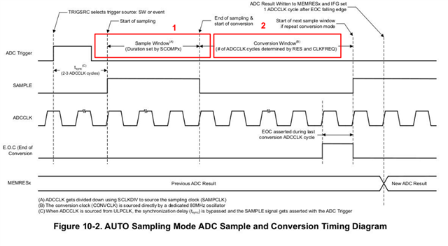
I have done below config settings, but I don't know how should I select or set the  DL_ADC12_setSampleTime0 can you help me with that to understand the adc calculation, I am getting confused with TRM?

  • 1) The argument to DL_ADC12_setSampleTime0 is denominated in ADCCLK ticks. If ADCCLK=16MHz, and you want (e.g.) a sample/hold period of Tsample=1us,  you would give it 16.

    2) The sample/hold period (in seconds) you want is largely dependent on your sensor's source impedance. The formula is given in MSPM0 Hardware Design Guide (SLAAE76B) Sec 6.1. Rpar and Cpar are artifacts of your circuitry, and Cs/h, Rin, and Ci can be found in the datasheet. A simple spreadsheet can compute this, and for the G3507, 10-bit,  Rpar=1kOhm, Cpar=5pF [my EE once told me to estimate Cpar=5pF if I don't know any better] mine computes a Tsample=166ns. These formulae tend to be conservative, so I generally round up.