


Part Number: AM2634
Other Parts Discussed in Thread: SYSCONFIG
Tool/software:
I am implementing PWM modulation for a three-level converter on the AM2634 Control Card, utilizing 6 ePWM units. These units are configured to operate in up-down mode with a period of 1ms, and they are synchronized with each other. The 'Enable Phase Shift Load' option is enabled on all 6 ePWM units, along with the shadow functionality.
After coding the calculation for the Compare registers, I tested the system by recording the PWM gate signals on an oscilloscope. I then saved and imported the data(gate signals on HSEC connector) into the simulation software (Plecs) to evaluate the accuracy of the generated voltage and verify the correctness of the gate signals from the AM2634.
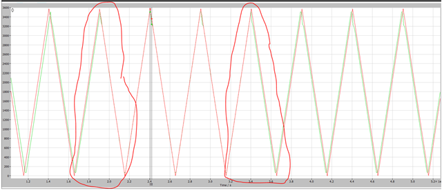
In Plecs, I connected the gate signals to an inverter and calculated the periodic average value of the generated phase voltage with 1ms averaging period (which corresponds to the PWM switching period). The comparison of the voltage generated by the gate signals and the reference voltage (the ref. voltage input to the modulator in the AM2634) is shown in the attached image. The green trace represents the reference voltage, while the red trace shows the voltage generated by the gate signals recorded from the AM2634 and imported into Plecs. As you can see, the modulator operates correctly most of the time, except for an error that appears approximately every 60°, or something similar. Each error last excactly one PWM period.

Furthermore, I have tried numerous different settings for the ePWM units, check ref. voltages, but the issue persists. One of the checks I performed involved saving the values of active compare registers of the AM2634 in arrays (in time interapt with a time interval 100 times smaller than the PWM switching period), exporting them to a .csv file, and importing them into the simulation software. In the simulation, I connected the values to the comparators, and in this case, the problem does not occur. This suggests that the calculation of the compare values is not the issue.
In the implementation on the AM2634, the reference alpha-beta voltages sent to the modulator are calculated in the PWM interrupt, which is triggered in the middle of the switching period (when the counter reaches maximum). The shadow functionality is enabled on all 6 PWM units, and it is configured so that the shadow-to-active load transition occurs when the counter reaches zero.
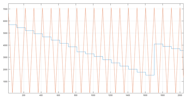
To verify this, I checked the behavior and it appears that the shadow functionality is not operating as expected (or maybe I'm reading shadow register?). Specifically, the Active compare registers for the ePWM units seem to be updated immediately, rather than when the counter reaches zero. This update happens approximately when the counters reach their maximum, right after the compare values are calculated in the ePWM interrupt. The image below illustrates the counter content of the ePWM0 unit and the values of the Active compare register of ePWM0. As it can be seen, it appears that the Active compare register is updated during the middle of the switching period, rather than at the end.
I obtained this data(counter content and Active compare register content of ePWM0) by saving the counter contents and Active Compare register values in arrays, then exporting them to a .csv file. The counter contents for ePWM0 were read from memory location 0x50000008, and the Active Compare register content were read from 0x500000D6. I also attempted to read the Compare register of ePWM0 using the EPWM_getCounterCompareValue command, and the result was the same.
The important settings of the ePWM0 unit (ePWM0 generates sync-out pulses for the remaining 5 ePWM units and generates an interapt in the middle of the switching period to update the Compare Values) are as shown in the following figure:
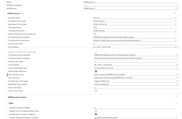
Is it possible that the shadow functionality is not working or is there some other problem I can not see?
I also noticed an strange behavior in the PWM unit counters, which I observed on two different units (out of six), and the same issue occurs with both (remaining four I didn't check). As shown in the image below, the ideal counter (perfectly symmetrical) is represented in red, while the ePWM0 unit counter on the AM2634 is shown in green. The green signal was obtained as described earlier, by writing to a array in the fast time interrupt and exporting the data to CSV.
It is evident that there are changes in slope in the signal. At this point, I am not sure whether this green signal is accurate, or if it’s caused by delays in the time interrupt used to sample the counter value (the sampling interrupt is set with the highest priority). If the green signal is correct as shown, then it seems that the counter becomes asymmetrical at times, meaning the duration of the count-down is not equal to the duration of the count-up. This can be clearly seen in the two marked periods.
Any help will be very welcome.


