


Part Number: AM263P4
Other Parts Discussed in Thread: UNIFLASH, SYSCONFIG
Tool/software:
We have a custom board with the AM263P4 ZCZ_F package and want to use the 8MB internal FLASH which is of type IS25LX064.
I didn't found any example project which is using the internal FLASH.
We are using CCS v12.8.1 and SDK 10.01.00.33
Our goal is to modify the sbl_uart_uniflash and sbl_ospi_multicore_elf SDK example projects in order to booting our application project which uses all 4 R5F cores in Standalone mode.
At the moment I'm not able to get the sbl_uart_uniflash SDK example project working. I have tried with many different settings but always get the error: [STATUS] ERROR: Flash verify failed !!! after the SBL tiimage is sent over UART.
Actually, I would expect that there is an example project somewhere that enables the boot process using UART Flashwriter and SBL OSPI with the internal 8MB FLASH, but maybe this device variant is just too new.
Therefore I've tried to retrieve the correct settings by my own as follows.
I have modified the AM263Px Control Card ospi_flash_diag SDK example project and run it on our custom board in order to detect the correct FLASH settings.
Basically I just migrated the SysConfig to the AM263P4 ZCZ_F Package, set the "--package ZCZ_F" flag in the project properties (CCS Build > SysConfig > Miscellaneous).
This gives me the following output:
[OSPI Flash DMA Transfer Test] Starting ...
[QSPI Flash DMA Transfer Test] Executing Flash Erase on first block...
[OSPI Flash DMA Transfer Test] Performing Write-Read Test...
[OSPI Flash DMA Transfer Test] Starting ...
[QSPI Flash DMA Transfer Test] Executing Flash Erase on first block...
[OSPI Flash DMA Transfer Test] Performing Write-Read Test...
[OSPI Flash Diagnostic Test] Starting ...
[OSPI Flash Diagnostic Test] Flash Manufacturer ID : 0x9D
[OSPI Flash Diagnostic Test] Flash Device ID       : 0x5A17
[OSPI Flash Diagnostic Test] Executing Flash Erase on first block...
[OSPI Flash Diagnostic Test] Done !!!
[OSPI Flash Diagnostic Test] Performing Write-Read Test...
[OSPI Flash Diagnostic Test] Write-Read Test Passed!
[QSPI Flash Diagnostic Test] SFDP Information :
================================================
                      SFDP
================================================
SFDP Major Revision                       : 0x1
SFDP Minor Revision                       : 0x9
Number of Parameter Headers in this Table : 4

Types of Additional Parameter Tables in this flash
---------------------------------------------------
4 BYTE ADDRESSING MODE INSTRUCTIONS TABLE
NOR SPI PROFILE TABLE
OCTAL DDR MODE COMMAND SEQUENCE TABLE

Parsing of OCTAL DDR MODE COMMAND SEQUENCE TABLE table not yet supported.
JSON Data for the flash :

{

        "flashSize": 8388608,
        "flashPageSize": 256,
        "flashManfId": "0x9D",
        "flashDeviceId": "0x5A17",
        "flashBlockSize": 131072,
        "flashSectorSize": 4096,
        "cmdBlockErase3B": "0xD8",
        "cmdBlockErase4B": "0xDC",
        "cmdSectorErase3B": "0x20",
        "cmdSectorErase4B": "0x21",
        "protos": {
                "p111": {
                        "isDtr": false,
                        "cmdRd": "0x03",
                        "cmdWr": "0x02",
                        "modeClksCmd": 0,
                        "modeClksRd": 0,
                        "dummyClksCmd": 0,
                        "dummyClksRd": 0,
                        "enableType": "0",
                        "enableSeq": "0x00",
                        "dummyCfg": null,
                        "protoCfg": null,
                        "strDtrCfg": null
                },
                "p112": null,
                "p114": null,
                "p118": {
                        "isDtr": false,
                        "cmdRd": "0x7C",
                        "cmdWr": "0x84",
                        "modeClksCmd": 0,
                        "modeClksRd": 1,
                        "dummyClksCmd": 0,
                        "dummyClksRd": 7,
                        "enableType": "0",
                        "enableSeq": "0x00",
                        "dummyCfg": null,
                        "protoCfg": null,
                        "strDtrCfg": null
                },
                "p444s": null,
                "p444d": null,
                "p888s": null,
                "p888d": {
                        "isDtr": false,
                        "cmdRd": "0x0B",
                        "cmdWr": "0x12",
                        "modeClksCmd": 0,
                        "modeClksRd": 0,
                        "dummyClksCmd": 8,
                        "dummyClksRd": 14,
                        "enableType": "0",
                        "enableSeq": "0x00",
                        "dummyCfg": {
                                "isAddrReg": false,
                                "cmdRegRd":"0x00",
                                "cmdRegWr":"0x00",
                                "cfgReg":"0x00000000",
                                "shift":0,
                                "mask":"0x00",
                                "bitP":14
                        },
                        "protoCfg": {
                                "isAddrReg": false,
                                "cmdRegRd": "0x00",
                                "cmdRegWr": "0x00",
                                "cfgReg": "0x00000000",
                                "shift": 0,
                                "mask": "0x00",
                                "bitP": 0
                        },
                        "strDtrCfg": {
                                "isAddrReg": false,
                                "cmdRegRd": "0x00",
                                "cmdRegWr": "0x00",
                                "cfgReg": "0x00000000",
                                "shift": 0,
                                "mask": "0x00",
                                "bitP": 0
                        }
                },
                "pCustom": {
                        "fxn": null
                }
        },
        "addrByteSupport": "1",
        "fourByteAddrEnSeq": "0xA1",
        "cmdExtType": "REPEAT",
        "resetType": "0x30",
        "deviceBusyType": "0",
        "cmdWren": "0x06",
        "cmdRdsr": "0x05",
        "srWip":  0,
        "srWel":  1,
        "cmdChipErase": "0xC7",
        "rdIdSettings": {
                "cmd": "0x9F",
                "numBytes": 5,
                "dummy4": 0,
                "dummy8": 0
        },
        "xspiWipRdCmd": "0x00",
        "xspiWipReg": "0x00000000",
        "xspiWipBit": 0,
        "flashDeviceBusyTimeout": 20000000,
        "flashPageProgTimeout": 120
}

All tests have passed!!
If I compare the settings with the {MCU_PLUS_SDK_AM263PX_INSTALLATION_PATH}/source/sysconfig/board/.meta/flash/IS25LX064.json, the following settings are different:
(the output of the ospi_flash_diag SDK example project is on the right side)
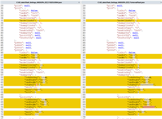
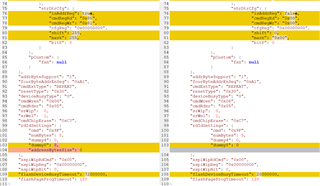
I've the following questions:
- How can you explain the above differences?
- What are the recommended settings for getting the best performance of internal FLASH access?
According to the IS25LX064 datasheet I would expect that for READ MEMORY operations the command "DDR OCTAL OUTPUT FAST READ" with code 0x9D
and for PROGRAM Operations the command "OCTAL INPUT FAST PROGRAM" with code 0x82 should be used. - In which SPI Protocol does the internal FLASH bootup after an MCU reset? (1S-1S-8S, 8D-8D-8D, ...) and
does it depend on which MCU BOOTMODE is selected (UART, OSPI (8S) - Octal Read Mode, xSPI 8D (SFDP)? - What are the recommended SysConfig OSPI settings for "Input Clock Frequency (Hz)" and "Input Clock Divider"?
- Is it recommended or required to activate the "Enable PHY Mode" in the SysConfig OSPI settings?
Thank you in Advance for your support.
Regards,
Daniel Reimann
