This thread has been locked.

If you have a related question, please click the "Ask a related question" button in the top right corner. The newly created question will be automatically linked to this question.

MSPM0G3507: Can't program MCU on the custom PCB with Error code

Part Number: MSPM0G3507
Other Parts Discussed in Thread: SYSCONFIG

Tool/software:

Every time I try to program my on-board MCU using XDS110 debugger on the launchpad, it gives me the error in the screenshot below. Could anyone help me solving this issue?

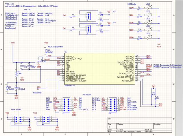
I connected 3.3V, GND, SWDIO, and SWCLK from the XDS110 to the custom board.

Thank you!

  • Hi Jaein,

    1. Check whether MCU is successfully welded

    2.Could you please try to also connect NRST to the XDS110?

    3. Double check the hardware schematic for MCU.

    Regards,

    Zoey

  • Hi Zoey,

    Thank you for your reply.

    Before adding more information and updates regarding this problem, I want to mention that I had no prior experience with MCUs and embedded systems before I started this project. So I'm afraid I might have no trivial background information or have missed some basic tasks I need to do.

    1. To me, it seems my MCU is successfully soldered, but is there any other way to check that with measurement tools? As MSPM0G3507 packages and pins are too small, I am not really sure if the power is actually getting supplied to the chip. Though I checked that the board's power pin headers share the correct 3.3V, it doesn't really tell if the chip is also getting a 3.3V supply.

    2. I connected NRST to the XDS110 too, but it shows the same error code even after 'Force Reset.'

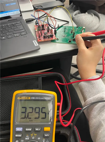
      Blue - GND, red - 3V3 (from XDS110), orange - NRST, gray - SWDIO, yellow - SWCLK

    3. I tried my best to design a correct schematic for the MCU referring to the user guide, datasheet, and the launchpad's schematics, but could you help me double check the hardware schematic for the MCU? Please find the attached screenshot of the schematic.

    (for better resolution: https://drive.google.com/file/d/1cg3_60IpdC6H2sy4aZ2P6TsGecvmanmk/view?usp=sharing)

    Thank you for your time.

    Best,

    Jaein

  • Hi Jaein,

    Have you ever successfully burned? or never? The schematic is correct from my perspective.

    And to make sure MCU soldered successfully:

    We first directly put the multimeter on the pins of the MCU to test whether its power supply is normal. In addition, we will first solder the MCU and its accessories, and then measure whether the resistance of the entire system is within the normal range to determine whether the MCU is successfully soldered.


    Back to the current problem of failed burning, excluding the reasons of hardware schematics and layout, the only thing I can think of is that the chip is not soldered successfully. Could you please check this again as a priority?

    Regards,

    Zoey

  • Hi Zoey,

    I've never burned a program successfully into the MCU before.

    I'm sorry if it is a too basic question, but how do you directly put the multimeter on the pins of the MCU when the pins are so small? Are there some thin DMM probe extensions for tiny pins like those of MSPM0G3507 available?

    Thank you for the comments and helps. I will check if the chip is soldered successfully by following the directions you provided.

    Also, would you please check if the layout is correctly done as well?

    (for better resolution: https://drive.google.com/file/d/1uy1zxBEZXX7iDQ5VGyULW5MMbeHNrqYI/view?usp=sharing)

    Thank you again.

    Best,

    Jaein

  • I'm sorry if it is a too basic question, but how do you directly put the multimeter on the pins of the MCU when the pins are so small? Are there some thin DMM probe extensions for tiny pins like those of MSPM0G3507 available?

    We did this under the microscope. Haha...

    Seen from the debug information, It seems MCU has been powered successfully, please check whether SWD pins have been soldered.

    And, the layout is ok from my side.

  • Thank you Zoey,

    Thanks to your recommendations, I rechecked the soldering and resoldered SWD pins, and it seems like they are finally connected now.

    However, when I try to burn the code into the chip, now CCS shows me a different error code:
    Texas Instruments XDS110 USB Debug Probe/CORTEX_M0P Error connecting to the target: (Error -6310) PRSC module failed to read a register. (Emulation package 20.0.0.3344)

    I'm trying to program the same code I ran on the LaunchPad to the MCU on my custom board, but those are different packages (though the model # - MSPM0G3507 - is the same). Would this error be caused by different configurations between those different packages?

    Also, please let me know if I should open a new question thread since the previous issue has been resolved and the error code has been changed.

    Thank you for your help, and I hope you have a great one!

    Best,

    Jaein

  • However, when I try to burn the code into the chip, now CCS shows me a different error code:
    Texas Instruments XDS110 USB Debug Probe/CORTEX_M0P Error connecting to the target: (Error -6310) PRSC module failed to read a register. (Emulation package 20.0.0.3344)

    Ohno, it seems that your device has been locked and can not access it anymore.

    If there is no problem with the software, this is usually due to poor signal quality caused by hardware during the communication process, which causes problems in the MCU download process.

    Also, please let me know if I should open a new question thread since the previous issue has been resolved and the error code has been changed.

    You can choose to open a new thread to have a further discussion.

    Regards,

    Zoey

  • Hi Zoey,

    Thank you so much for your answers.

    Could you let me know what 'MCU being locked' mean? Does it mean the chip is dead and needs to be replaced?

    I found out that I didn't change the package specification in sysconfig even though I'm using a different package (but the same chip) from the one on the launchpad. Would that might be the cause of that error code?

    Is that error code (or the state being locked) something that can be fixed or only able to be fixed by the chip replacement?

    I appreciate your help.

    Best,

    Jaein

  • Hi Jaein,

    I am sorry to say that the chip is dead and needs to be replaced.

    The package specification in sysconfig won't influence the burning. 

    Zoey

  • Confirm that SWDIO and SWCLK are properly connected. Check if GND is shared between the XDS110 debugger and your custom board. Also, check if there is no manufacturing error in your PCB. 

    vectorbluehub.com/pcb-test-what-it-is-and-how-it-helps

    www.pcbway.com/.../What_are_PCB_Test_Coupons_PCB_Knowledge_e14999fe.html