This thread has been locked.

If you have a related question, please click the "Ask a related question" button in the top right corner. The newly created question will be automatically linked to this question.

AM263P2: ADC pins assignment clarification

Genius 17675 points
Part Number: AM263P2

Tool/software:

Hi Experts,

Question2 from customer about the AM263Px Sitara package:

Q1:
I was wondering for the 5x 12-bit adc converters, do all of them have the option to be used as differential channels? That means can I get 5x (3x differential channels)?

Q2:
I says in the data sheet that there is "1x Resolver subsystem (ZCZ-S and ZCZ-F packages) with:– 2x Resolver to Digital Converter (RDC) OR – 2x 12-bit ADCs can also be used for general purpose". My question is if I use the 2x12 bit ADC for general purpose does that give me additional 2x ADCs on top of the 5x 12-bit ADCs?

Thank you.

Regards,
Archie A.

  • Hey Archie,

    1) Yes, this is correct. For the ADC's there are a total 30 single-ended channels or 15 differential-ended channels.

    2) Yes, this is correct. The two resolver ADCs (ADC_R[0:1]) can be used as general purpose ADC's (4x channels each @ max 3MSPS). This creates a total of 38 single-ended channels or 19 differential-ended channels when used together with the general ADC's.

    Best Regards,

    Zackary Fleenor

  • Nice!

    Thanks, Zackary, for your prompt confirmation.

    Regards,
    Archie A.

  • Hello Zackary,

    We have followed up.

    I was wondering what is the common mode and differential mode ranges on the ADC modules in AM263Px Sitara package. The reason I'm asking is that we are utilizing the differential feature in the ADC (use the 3  differential pairs in one adc module to interface measured ac voltages/currents).Also, where I can find this information in the datasheet if they exist?

    Regards,
    Archie A.

  • Hey Archie,

    *Assuming VREFHI is 1.8 V.

    In Single Ended Mode:

    The voltage range is 0 to 3.3V.

    In Differential Mode:

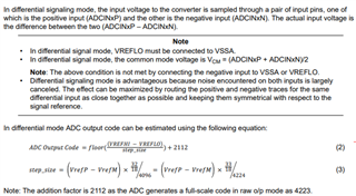
    The common mode is defined as (Vinp+Vinm)/2 and must always be (VRefP*33/18/2 ± 25mV).

    The maximum positive input is when Vin+=3.3V and Vin-=0 and the maximum negative input is when Vin+=0V and Vin-=3.3V. This range is equally divided in 4224 levels by the ADC.

    Some of this information is located in the TRM (pg. 469). Note, screenshot taken from AM263x TRM which has updated equation figures (this will come in the next release of the AM263Px TRM). I agree this is something that should probably also be included in the datasheet. I will file a ticket for that and see what the team says.

    Best Regards,

    Zackary Fleenor