Part Number: AM2632
Other Parts Discussed in Thread: SYSCONFIG
Tool/software:
Dear TI Support Team,
I hope this email finds you well.
I am currently working on configuring a GPIO interrupt triggered by a rising edge. In the existing example code, the implementation uses GPIO-bank-INTR. However, I need to configure a single GPIO pin to trigger its own dedicated interrupt instead of sharing a bank-level interrupt.
Could you kindly clarify the following questions?
-
How should I configure a single GPIO to map to a unique interrupt (instead of a bank)?
-
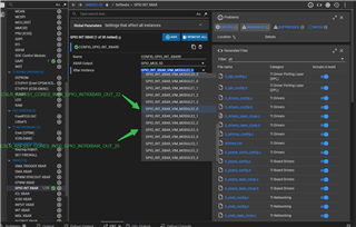
In SysConfig, there is a "GPIO INT XBAR" section. I would like to understand:
-
How do the XBAR Output and XBar Instance parameters correspond to each other?
-
-
Could you provide guidance on the interrupt configuration steps in the code (e.g., registering ISRs, enabling interrupts, etc.)?
- I have also looked at the link description below and I would like to know how gPepiaPinIntrNum and gPepiaBankIntrNum are configured and their corresponding relationship with syscfg software-dl.ti.com/.../DRIVERS_GPIO_PAGE.html
void gpio_bank_interrupt_init(void)
{
    int32_t         retVal;
    uint32_t        pinNum = gGpioPinNum, bankNum;
    HwiP_Params     hwiPrms;

    bankNum = GPIO_GET_BANK_INDEX(pinNum);

    /* Interrupt setup */
    GPIO_setDirMode(gGpioBaseAddr, pinNum, GPIO_DIRECTION_INPUT);
    GPIO_setTrigType(gGpioBaseAddr, pinNum, GPIO_TRIG_TYPE_RISE_EDGE);
    GPIO_bankIntrEnable(gGpioBaseAddr, bankNum);

    /* Register bank interrupt */
    HwiP_Params_init(&hwiPrms);
    hwiPrms.intNum = gGpioBankIntrNum;
    hwiPrms.callback = &GPIO_bankIsrFxn;
    hwiPrms.args = (void *) pinNum;
    retVal = HwiP_construct(&gGpioHwiObject, &hwiPrms);
    if(SystemP_SUCCESS != retVal)
    {
        DebugP_assert(FALSE);
    }
}

void gpio_pin_interrupt_init(void)
{
    int32_t         retVal;
    uint32_t        pinNum = gGpioPinNum, bankNum;
    HwiP_Params     hwiPrms;

    bankNum = GPIO_GET_BANK_INDEX(pinNum);

    /* Interrupt setup */
    GPIO_setDirMode(gGpioBaseAddr, pinNum, GPIO_DIRECTION_INPUT);
    GPIO_setTrigType(gGpioBaseAddr, pinNum, GPIO_TRIG_TYPE_RISE_EDGE);
    GPIO_bankIntrEnable(gGpioBaseAddr, bankNum);

    /* Register pin interrupt */
    HwiP_Params_init(&hwiPrms);
    hwiPrms.intNum = gGpioPinIntrNum;
    hwiPrms.callback = &GPIO_pinIsrFxn;
    hwiPrms.args = (void *) pinNum;
    retVal = HwiP_construct(&gGpioHwiObject, &hwiPrms);
    if(SystemP_SUCCESS != retVal)
    {
        DebugP_assert(FALSE);
    }
}
My requirement is r5fss1-0, PR0_PRU0_GPIO4,pin interrupt。
Please provide me with specific syscfg and gPepiaPinIntrNum。
Thank you for your time and support!
Best regards,
zx