Part Number: MSPM0G3507
Tool/software:
Hello Team,
While I reading MSPM0 G series TRM, I found that Figures(Timing diagrams) in TRM have different CCP input~Sync'd CCP input TIMCLK cycle delay.
While FIg 27-13 have one cycle delay between CCP and Sync'd CCP input, Figure 27-14 have about 1.7 cycle delay.
Please provide feedback that I have understood it correctly.
1. Is this because of synchronizer?
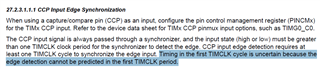
In 27.2.3.1.1.1 CCP Input Edge Synchronization section of TRM, synchronizer can detect the state which last at least 1 cycle.
In Fig 27-13, CCP input go HIGH with TIMCLK rising edge at same time, so Synchronizer can output Sync'd CCP input at next rising edge of TIMCLK.
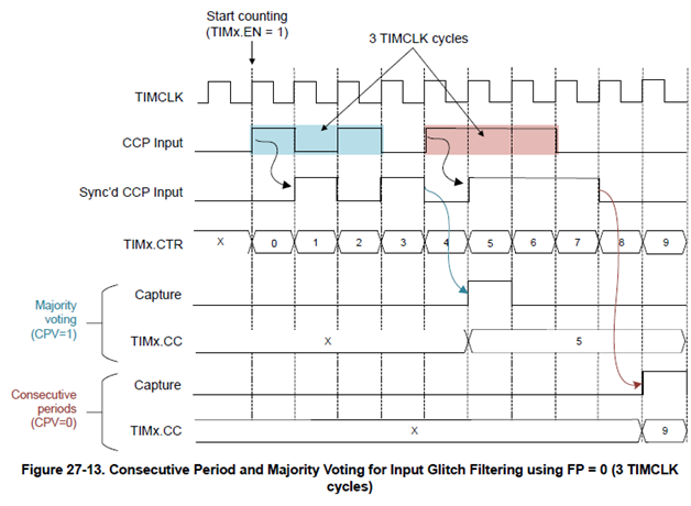
But 27-14, CCP input go HIGH after 0.3 cycle after the TIMCLK rising edge, so Synchronizer not sure of CCP input is HIGH(because signal is less than 1 cycle),
so have to wait another clk cycle to ouput Sync'd CCP input.
Am I understanding correctly about synchronizer work flow?
2. Is there way to change amount of cycle for input detecting in synchronizer?
Thank you!