This thread has been locked.

If you have a related question, please click the "Ask a related question" button in the top right corner. The newly created question will be automatically linked to this question.

AM2634: AM263X & F28P65X : CAN communication issue

Part Number: AM2634
Other Parts Discussed in Thread: LAUNCHXL-F28P65X, LP-AM263, SYSCONFIG

Tool/software:

Hi Team,

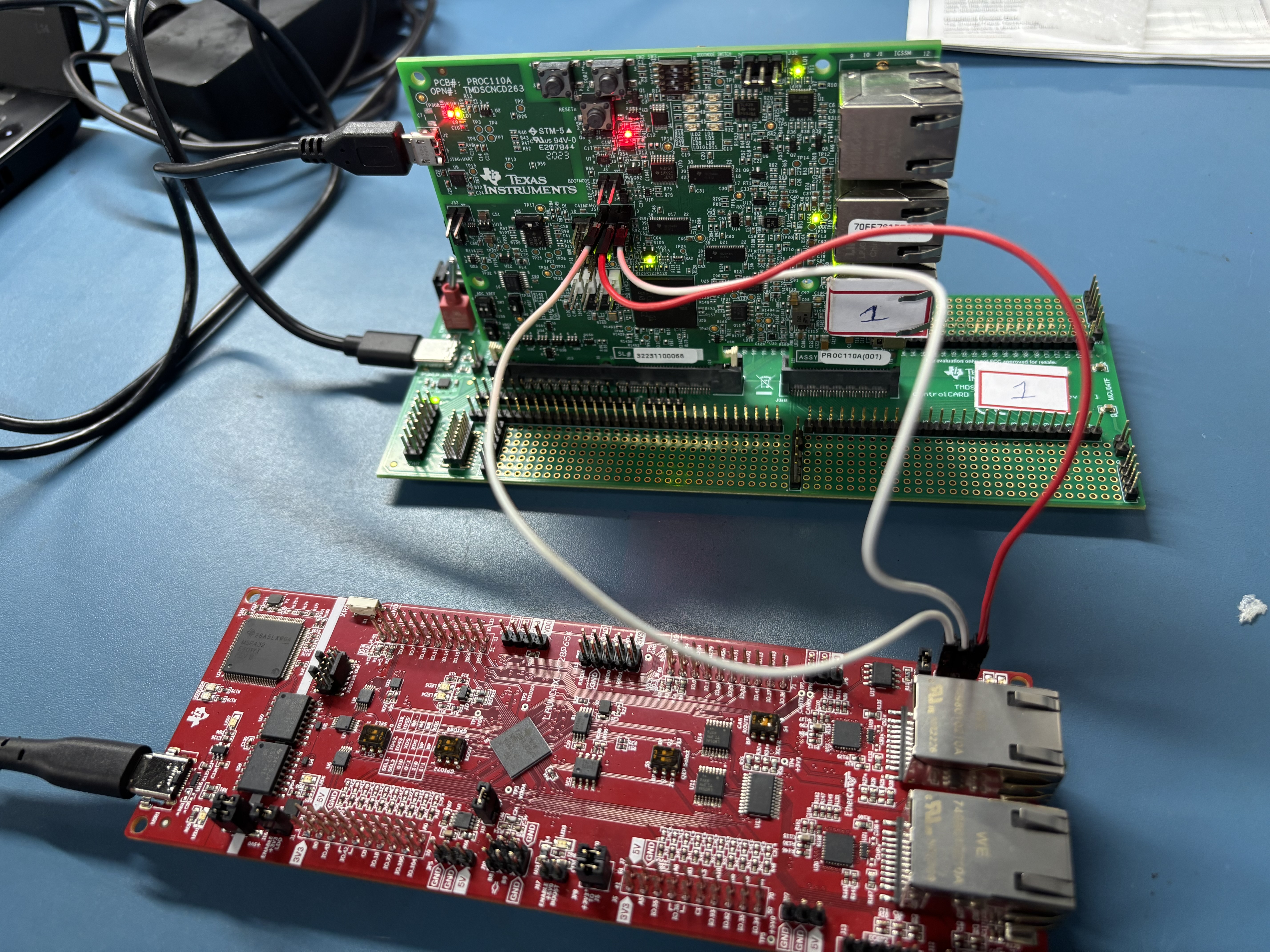
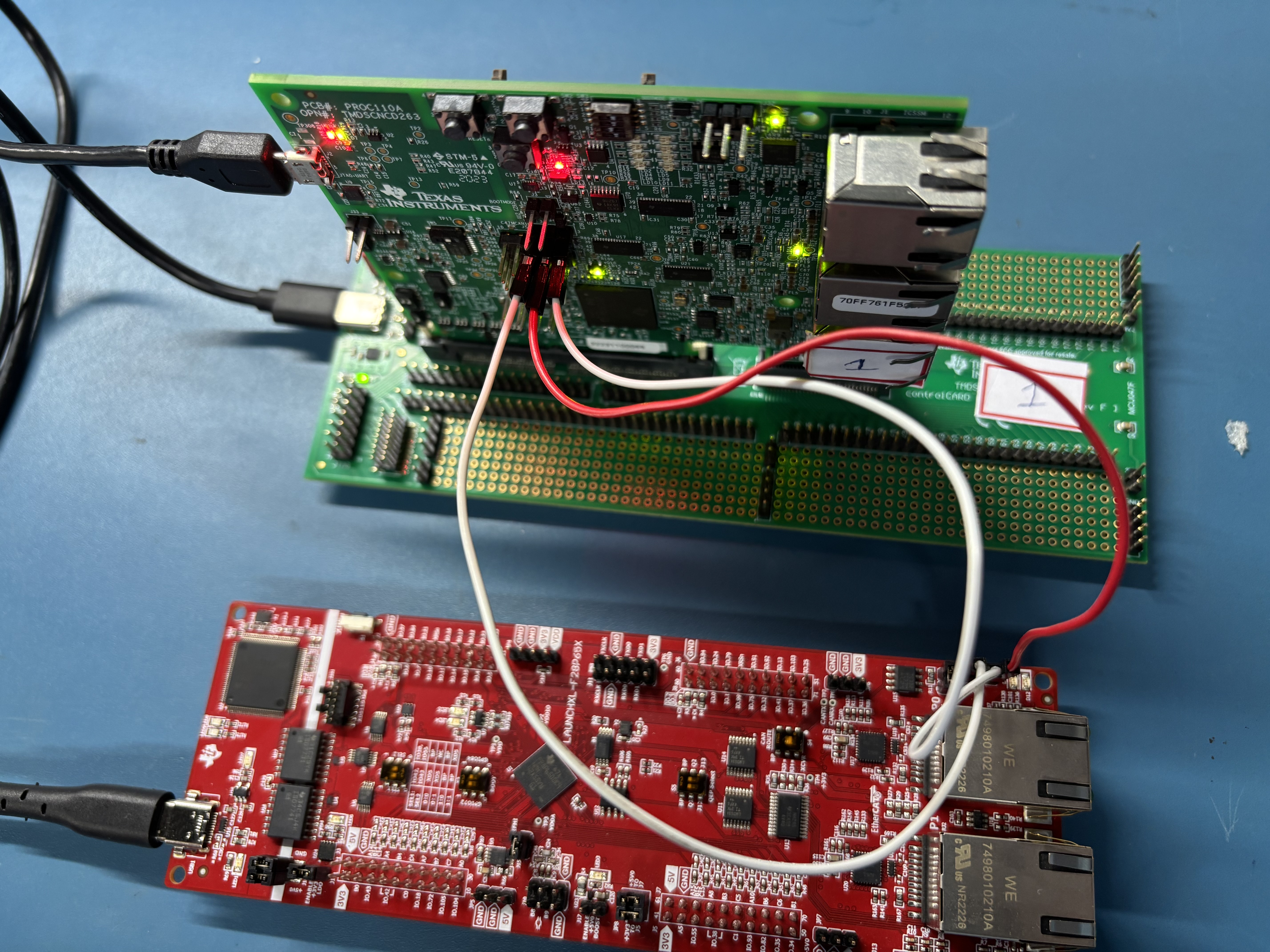
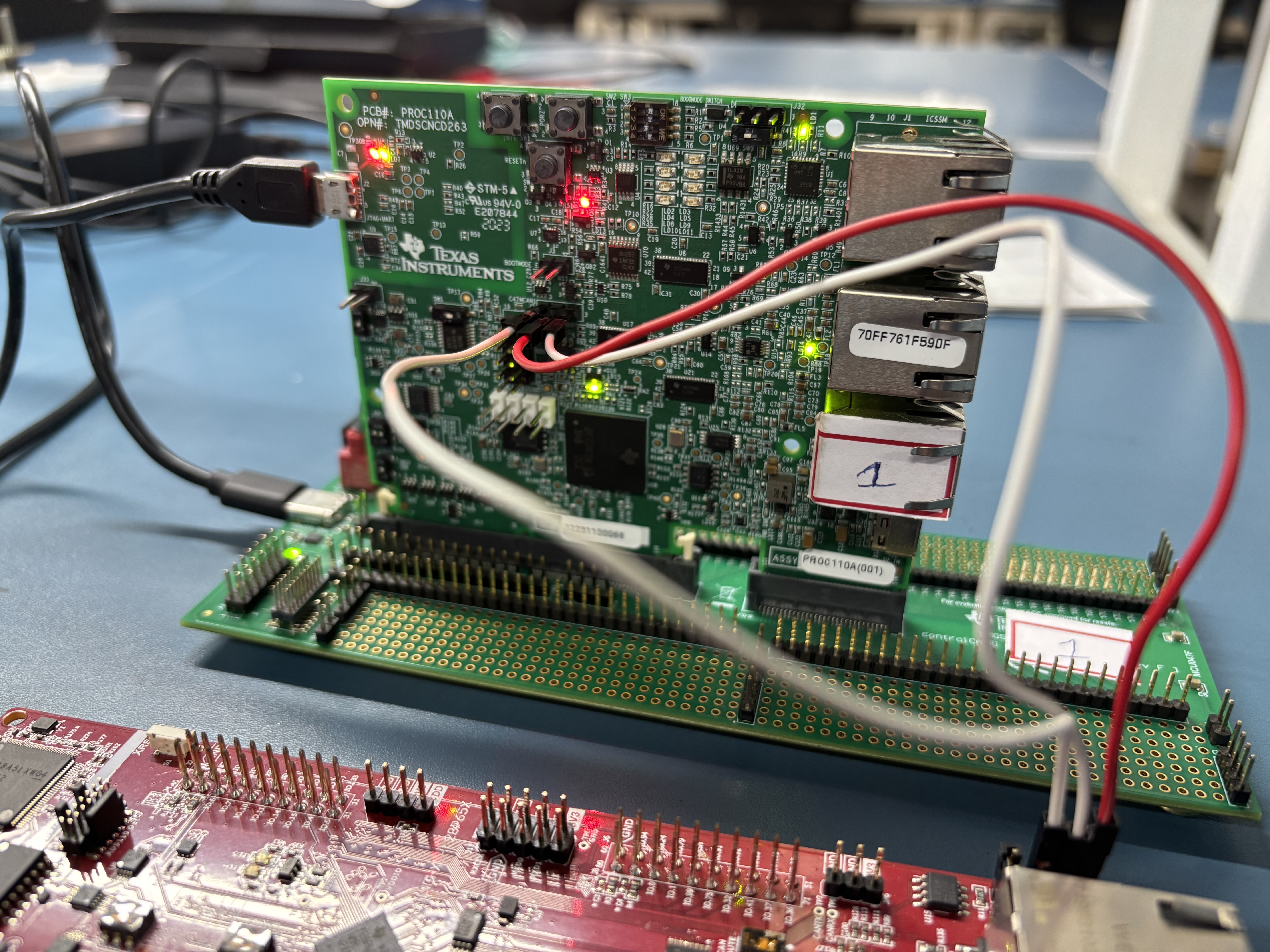
We are experiencing issues connecting the AM2634 board with the LaunchXL-F28P65X via CAN. We are unable to transmit data successfully over CAN. What configurations should we check on both boards to enable CAN communication? Are there any other factors we should consider?

  • Hello Anjana,

    For starters, which CAN ports on each board are you using?

    I am only familiar with the LP-AM263 personally but I can work with an expert who knows the other board and check for any dependencies once I know which two ports to focus on.

    Best Regards,

    Ralph Jacobi

  • Hi Ralph

    We have externally connected the CAN ports, with MCAN1 on the AM263X (MCAN1_CAN_H, MCAN1_CAN_L, GND) routed through J5 and CAN_HI, CAN_LO, and GND on the F28P65X connected via J14.

    Internally, in the SysConfig file:

    • On the AM263X, MCAN1_RX and MCAN1_TX have been enabled.
    • On the F28P65X, GPIO4 and GPIO5 have been configured for CAN communication.
  • Hello Anjana,

    That explains the issue then. You are using the correct CAN signals on the F28P65X LaunchPad as the J14 header is the one with a CAN transceiver on it.

    But on LP-AM263 you need to use MCAN0 and the J33 terminal headers. The MCAN1/J5 pins do not have a CAN transceiver attached to them. The only CAN transceiver on LP-AM263 is on MCAN0 and brought out to the J33 headers.

    Alternatively, you could connect the signals from MCAN1 from J5 into an off-board CAN transceiver that then connect to the F28P65X LaunchPad.

    Both sides of the CAN bus needs a transceiver and without that, communication is impossible.

    Best Regards,

    Ralph Jacobi

  • Hi Ralph

    We are using AM263X_CC, not LP-AM263. The MCAN1 interface on the AM263X_CC is connected via MCAN1_CAN_H, MCAN1_CAN_L, and GND, routed through J5.

    We tested the CAN loopback mode on both boards, and it is working correctly. However, when connecting the two boards for CAN communication, we are unable to transmit data.

    While attempting to send data from AM263X_CC to F28P65X, we encountered the interrupt MCAN_INTR_SRC_PROTOCOL_ERR_DATA, and the transmission is failing due to the condition can_bus->tx_done != true not being met.

    Could please help on debugging it.

    Thanks in advance.

  • Hello Anjana,

    Thanks for clarifying the EVM used, sorry I wrongly assumed the LP-AM263 was being used. I didn't realize the MCAN1 header on the CC was J5.

    For the CC, there is an extra step needed to enable the MCAN transceiver which involves writing the I2C expander to control the MCAN1_STB pin.

    This is handled in the attached c file which is part of our SDK and can be found in examples such as mcan_external_read_write.

    Check to see if this is implemented and if not, please implement it on the AM263x CC example and then try again. If this doesn't clear up the issue I'll need to loop in a CAN expert who can further debug the issue. 

    /*
     *  Copyright (C) 2023 Texas Instruments Incorporated
     *
     *  Redistribution and use in source and binary forms, with or without
     *  modification, are permitted provided that the following conditions
     *  are met:
     *
     *    Redistributions of source code must retain the above copyright
     *    notice, this list of conditions and the following disclaimer.
     *
     *    Redistributions in binary form must reproduce the above copyright
     *    notice, this list of conditions and the following disclaimer in the
     *    documentation and/or other materials provided with the
     *    distribution.
     *
     *    Neither the name of Texas Instruments Incorporated nor the names of
     *    its contributors may be used to endorse or promote products derived
     *    from this software without specific prior written permission.
     *
     *  THIS SOFTWARE IS PROVIDED BY THE COPYRIGHT HOLDERS AND CONTRIBUTORS
     *  "AS IS" AND ANY EXPRESS OR IMPLIED WARRANTIES, INCLUDING, BUT NOT
     *  LIMITED TO, THE IMPLIED WARRANTIES OF MERCHANTABILITY AND FITNESS FOR
     *  A PARTICULAR PURPOSE ARE DISCLAIMED. IN NO EVENT SHALL THE COPYRIGHT
     *  OWNER OR CONTRIBUTORS BE LIABLE FOR ANY DIRECT, INDIRECT, INCIDENTAL,
     *  SPECIAL, EXEMPLARY, OR CONSEQUENTIAL DAMAGES (INCLUDING, BUT NOT
     *  LIMITED TO, PROCUREMENT OF SUBSTITUTE GOODS OR SERVICES; LOSS OF USE,
     *  DATA, OR PROFITS; OR BUSINESS INTERRUPTION) HOWEVER CAUSED AND ON ANY
     *  THEORY OF LIABILITY, WHETHER IN CONTRACT, STRICT LIABILITY, OR TORT
     *  (INCLUDING NEGLIGENCE OR OTHERWISE) ARISING IN ANY WAY OUT OF THE USE
     *  OF THIS SOFTWARE, EVEN IF ADVISED OF THE POSSIBILITY OF SUCH DAMAGE.
     */
    
    /* This example demonstrates the CAN message communication to external CAN
     * controller in with the following configuration.
     * CAN FD Message Format.
     * Message ID Type is Standard, Msg Id 0xC0.
     * MCAN is configured in Interrupt Mode.
     * MCAN Interrupt Line Number 0.
     * Arbitration Bit Rate 1Mbps.
     * Data Bit Rate 5Mbps.
     * Buffer mode is used for Tx and RX to store message in message RAM.
     * Instance MCAN1 is set as a Commander in Transmit Mode. Message is transmitted and received
     * back from external CAN controller. Once message is transmitted the example will wait for
     * recieving the messages from external PC. Have to manually transmit ten messages from external
     * PC for test to finish. When the received message id and the data matches with the transmitted
     * one, then the example is completed.
     */
    
    #include <stdio.h>
    #include <kernel/dpl/DebugP.h>
    #include <kernel/dpl/AddrTranslateP.h>
    #include <kernel/dpl/SemaphoreP.h>
    #include <drivers/mcan.h>
    #include "ti_drivers_config.h"
    #include "ti_drivers_open_close.h"
    #include "ti_board_open_close.h"
    
    #define APP_MCAN_BASE_ADDR                       (CONFIG_MCAN0_BASE_ADDR)
    #define APP_MCAN_INTR_NUM                        (CONFIG_MCAN0_INTR)
    #define APP_MCAN_MSG_LOOP_COUNT                  (10U)
    #define APP_MCAN_LOOPBACK_MODE_DISABLE           (FALSE)
    
    /* Allocate Message RAM memory section to filter elements, buffers, FIFO */
    /* Maximum STD Filter Element can be configured is 128 */
    #define APP_MCAN_STD_ID_FILTER_CNT               (1U)
    /* Maximum EXT Filter Element can be configured is 64 */
    #define APP_MCAN_EXT_ID_FILTER_CNT               (0U)
    /* Maximum TX Buffer + TX FIFO, combined can be configured is 32 */
    #define APP_MCAN_TX_BUFF_CNT                     (1U)
    #define APP_MCAN_TX_FIFO_CNT                     (0U)
    /* Maximum TX Event FIFO can be configured is 32 */
    #define APP_MCAN_TX_EVENT_FIFO_CNT               (0U)
    /* Maximum RX FIFO 0 can be configured is 64 */
    #define APP_MCAN_FIFO_0_CNT                      (0U)
    /* Maximum RX FIFO 1 can be configured is 64 and
     * rest of the memory is allocated to RX buffer which is again of max size 64 */
    #define APP_MCAN_FIFO_1_CNT                      (0U)
    
    /* Standard Id configured in this app */
    #define APP_MCAN_STD_ID                          (0xC0U)
    #define APP_MCAN_STD_ID_MASK                     (0x7FFU)
    #define APP_MCAN_STD_ID_SHIFT                    (18U)
    
    #define APP_MCAN_EXT_ID_MASK                     (0x1FFFFFFFU)
    
    /* In the CAN FD format, the Data length coding differs from the standard CAN.
     * In case of standard CAN it is 8 bytes */
    static const uint8_t gMcanDataSize[16U] = {0U,  1U,  2U,  3U,
                                               4U,  5U,  6U,  7U,
                                               8U,  12U, 16U, 20U,
                                               24U, 32U, 48U, 64U};
    
    /* Semaphore to indicate transfer completion */
    static SemaphoreP_Object gMcanTxDoneSem, gMcanRxDoneSem;
    static HwiP_Object       gMcanHwiObject;
    static uint32_t          gMcanBaseAddr;
    
    /* Static Function Declarations */
    static void    App_mcanIntrISR(void *arg);
    static void    App_mcanConfig(Bool enableInternalLpbk);
    static void    App_mcanInitMsgRamConfigParams(
                   MCAN_MsgRAMConfigParams *msgRAMConfigParams);
    static void    App_mcanEnableIntr(void);
    static void    App_mcanConfigTxMsg(MCAN_TxBufElement *txMsg);
    static void    App_mcanCompareMsg(MCAN_TxBufElement *txMsg,
                                      MCAN_RxBufElement *rxMsg);
    static void    App_mcanInitStdFilterElemParams(
                                      MCAN_StdMsgIDFilterElement *stdFiltElem,
                                      uint32_t bufNum);
    
    void mcanEnableTransceiver(void);
    
    void mcan_external_read_write_main(void *args)
    {
        int32_t                 status = SystemP_SUCCESS;
        HwiP_Params             hwiPrms;
        MCAN_TxBufElement       txMsg;
        MCAN_ProtocolStatus     protStatus;
        MCAN_RxBufElement       rxMsg;
        MCAN_RxNewDataStatus    newDataStatus;
        MCAN_ErrCntStatus       errCounter;
        uint32_t                i, bufNum, fifoNum, bitPos = 0U;
    
        /* Open drivers to open the UART driver for console */
        Drivers_open();
        Board_driversOpen();
    
        mcanEnableTransceiver();
    
        DebugP_log("[MCAN] External read - write test, application started ...\r\n");
    
        /* Construct Tx/Rx Semaphore objects */
        status = SemaphoreP_constructBinary(&gMcanTxDoneSem, 0);
        DebugP_assert(SystemP_SUCCESS == status);
        status = SemaphoreP_constructBinary(&gMcanRxDoneSem, 0);
        DebugP_assert(SystemP_SUCCESS == status);
    
        /* Register interrupt */
        HwiP_Params_init(&hwiPrms);
        hwiPrms.intNum      = APP_MCAN_INTR_NUM;
        hwiPrms.callback    = &App_mcanIntrISR;
        status              = HwiP_construct(&gMcanHwiObject, &hwiPrms);
        DebugP_assert(status == SystemP_SUCCESS);
    
        /* Assign MCAN instance address */
        gMcanBaseAddr = (uint32_t) AddrTranslateP_getLocalAddr(APP_MCAN_BASE_ADDR);
    
        /* Configure MCAN module, Enable External LoopBack Mode */
        App_mcanConfig(APP_MCAN_LOOPBACK_MODE_DISABLE);
    
        /* Enable Interrupts */
        App_mcanEnableIntr();
    
        DebugP_log("After transmitting the messages, it will wait to recieve ten messages for test to pass ...\r\n");
    
        /* Transmit And Receive Message */
        for (i = 0U; i < APP_MCAN_MSG_LOOP_COUNT; i++)
        {
            /* Configure Tx Msg to transmit */
            App_mcanConfigTxMsg(&txMsg);
    
            /* Select buffer number, 32 buffers available */
            bufNum = 0U;
            /* Enable Transmission interrupt for the selected buf num,
             * If FIFO is used, then need to send FIFO start index until FIFO count */
            status = MCAN_txBufTransIntrEnable(gMcanBaseAddr, bufNum, (uint32_t)TRUE);
            DebugP_assert(status == CSL_PASS);
    
            /* Write message to Msg RAM */
            MCAN_writeMsgRam(gMcanBaseAddr, MCAN_MEM_TYPE_BUF, bufNum, &txMsg);
    
            /* Add request for transmission, This function will trigger transmission */
            status = MCAN_txBufAddReq(gMcanBaseAddr, bufNum);
            DebugP_assert(status == CSL_PASS);
    
            /* Wait for Tx completion */
            SemaphoreP_pend(&gMcanTxDoneSem, SystemP_WAIT_FOREVER);
    
            MCAN_getProtocolStatus(gMcanBaseAddr, &protStatus);
            /* Checking for Tx Errors */
            if (((MCAN_ERR_CODE_NO_ERROR != protStatus.lastErrCode) ||
                 (MCAN_ERR_CODE_NO_CHANGE != protStatus.lastErrCode)) &&
                ((MCAN_ERR_CODE_NO_ERROR != protStatus.dlec) ||
                 (MCAN_ERR_CODE_NO_CHANGE != protStatus.dlec)) &&
                (0U != protStatus.pxe))
            {
                 DebugP_assert(FALSE);
            }
    
            /* Wait for Rx completion */
            SemaphoreP_pend(&gMcanRxDoneSem, SystemP_WAIT_FOREVER);
    
            /* Checking for Rx Errors */
            MCAN_getErrCounters(gMcanBaseAddr, &errCounter);
            DebugP_assert((0U == errCounter.recErrCnt) &&
                          (0U == errCounter.canErrLogCnt));
    
            /* Get the new data staus, indicates buffer num which received message */
            MCAN_getNewDataStatus(gMcanBaseAddr, &newDataStatus);
            MCAN_clearNewDataStatus(gMcanBaseAddr, &newDataStatus);
    
            /* Select buffer and fifo number, Buffer is used in this app */
            bufNum = 0U;
            fifoNum = MCAN_RX_FIFO_NUM_0;
    
            bitPos = (1U << bufNum);
            if (bitPos == (newDataStatus.statusLow & bitPos))
            {
                MCAN_readMsgRam(gMcanBaseAddr, MCAN_MEM_TYPE_BUF, bufNum, fifoNum, &rxMsg);
            }
            else
            {
                DebugP_assert(FALSE);
            }
    
            /* Compare Tx/Rx data */
            App_mcanCompareMsg(&txMsg, &rxMsg);
        }
        /* De-Construct Tx/Rx Semaphore objects */
        HwiP_destruct(&gMcanHwiObject);
        SemaphoreP_destruct(&gMcanTxDoneSem);
        SemaphoreP_destruct(&gMcanRxDoneSem);
        MCAN_reset(gMcanBaseAddr);
    
        DebugP_log("All tests have passed!!\r\n");
    
        Board_driversClose();
        Drivers_close();
    
        return;
    }
    
    static void App_mcanConfig(Bool enableInternalLpbk)
    {
        MCAN_StdMsgIDFilterElement stdFiltElem[APP_MCAN_STD_ID_FILTER_CNT] = {0U};
        MCAN_InitParams            initParams = {0U};
        MCAN_ConfigParams          configParams = {0U};
        MCAN_MsgRAMConfigParams    msgRAMConfigParams = {0U};
        MCAN_BitTimingParams       bitTimes = {0U};
        uint32_t                   i;
    
        /* Initialize MCAN module initParams */
        MCAN_initOperModeParams(&initParams);
        /* CAN FD Mode and Bit Rate Switch Enabled */
        initParams.fdMode          = TRUE;
        initParams.brsEnable       = TRUE;
    
        /* Initialize MCAN module Global Filter Params */
        MCAN_initGlobalFilterConfigParams(&configParams);
    
        /* Initialize MCAN module Bit Time Params */
        /* Configuring default 1Mbps and 5Mbps as nominal and data bit-rate resp */
        MCAN_initSetBitTimeParams(&bitTimes);
    
        /* Initialize MCAN module Message Ram Params */
        App_mcanInitMsgRamConfigParams(&msgRAMConfigParams);
    
        /* Initialize Filter element to receive msg, should be same as tx msg id */
        for (i = 0U; i < APP_MCAN_STD_ID_FILTER_CNT; i++)
        {
            App_mcanInitStdFilterElemParams(&stdFiltElem[i], i);
        }
        /* wait for memory initialization to happen */
        while (FALSE == MCAN_isMemInitDone(gMcanBaseAddr))
        {}
    
        /* Put MCAN in SW initialization mode */
        MCAN_setOpMode(gMcanBaseAddr, MCAN_OPERATION_MODE_SW_INIT);
        while (MCAN_OPERATION_MODE_SW_INIT != MCAN_getOpMode(gMcanBaseAddr))
        {}
    
        /* Initialize MCAN module */
        MCAN_init(gMcanBaseAddr, &initParams);
        /* Configure MCAN module Gloabal Filter */
        MCAN_config(gMcanBaseAddr, &configParams);
        /* Configure Bit timings */
        MCAN_setBitTime(gMcanBaseAddr, &bitTimes);
        /* Configure Message RAM Sections */
        MCAN_msgRAMConfig(gMcanBaseAddr, &msgRAMConfigParams);
        /* Set Extended ID Mask */
        MCAN_setExtIDAndMask(gMcanBaseAddr, APP_MCAN_EXT_ID_MASK);
    
        /* Configure Standard ID filter element */
        for (i = 0U; i < APP_MCAN_STD_ID_FILTER_CNT; i++)
        {
            MCAN_addStdMsgIDFilter(gMcanBaseAddr, i, &stdFiltElem[i]);
        }
        if (TRUE == enableInternalLpbk)
        {
            MCAN_lpbkModeEnable(gMcanBaseAddr, MCAN_LPBK_MODE_INTERNAL, TRUE);
        }
    
        /* Take MCAN out of the SW initialization mode */
        MCAN_setOpMode(gMcanBaseAddr, MCAN_OPERATION_MODE_NORMAL);
        while (MCAN_OPERATION_MODE_NORMAL != MCAN_getOpMode(gMcanBaseAddr))
        {}
    
        return;
    }
    
    static void App_mcanConfigTxMsg(MCAN_TxBufElement *txMsg)
    {
        uint32_t i;
    
        /* Initialize message to transmit */
        MCAN_initTxBufElement(txMsg);
        /* Standard message identifier 11 bit, stored into ID[28-18] */
        txMsg->id  = ((APP_MCAN_STD_ID & MCAN_STD_ID_MASK) << MCAN_STD_ID_SHIFT);
        txMsg->dlc = MCAN_DATA_SIZE_64BYTES; /* Payload size is 64 bytes */
        txMsg->fdf = TRUE; /* CAN FD Frame Format */
        txMsg->xtd = FALSE; /* Extended id not configured */
        for (i = 0U; i < gMcanDataSize[MCAN_DATA_SIZE_64BYTES]; i++)
        {
            txMsg->data[i] = i;
        }
    
        return;
    }
    
    static void App_mcanInitStdFilterElemParams(MCAN_StdMsgIDFilterElement *stdFiltElem,
                                                uint32_t bufNum)
    {
        /* sfid1 defines the ID of the standard message to be stored. */
        stdFiltElem->sfid1 = APP_MCAN_STD_ID;
        /* As buffer mode is selected, sfid2 should be bufNum[0 - 63] */
        stdFiltElem->sfid2 = bufNum;
        /* Store message in buffer */
        stdFiltElem->sfec  = MCAN_STD_FILT_ELEM_BUFFER;
        /* Below configuration is ignored if message is stored in buffer */
        stdFiltElem->sft   = MCAN_STD_FILT_TYPE_RANGE;
    
        return;
    }
    
    static void App_mcanEnableIntr(void)
    {
        MCAN_enableIntr(gMcanBaseAddr, MCAN_INTR_MASK_ALL, (uint32_t)TRUE);
        MCAN_enableIntr(gMcanBaseAddr,
                        MCAN_INTR_SRC_RES_ADDR_ACCESS, (uint32_t)FALSE);
        /* Select Interrupt Line 0 */
        MCAN_selectIntrLine(gMcanBaseAddr, MCAN_INTR_MASK_ALL, MCAN_INTR_LINE_NUM_0);
        /* Enable Interrupt Line */
        MCAN_enableIntrLine(gMcanBaseAddr, MCAN_INTR_LINE_NUM_0, (uint32_t)TRUE);
    
        return;
    }
    
    static void App_mcanInitMsgRamConfigParams(MCAN_MsgRAMConfigParams
                                               *msgRAMConfigParams)
    {
        int32_t status;
    
        MCAN_initMsgRamConfigParams(msgRAMConfigParams);
    
        /* Configure the user required msg ram params */
        msgRAMConfigParams->lss = APP_MCAN_STD_ID_FILTER_CNT;
        msgRAMConfigParams->lse = APP_MCAN_EXT_ID_FILTER_CNT;
        msgRAMConfigParams->txBufCnt = APP_MCAN_TX_BUFF_CNT;
        msgRAMConfigParams->txFIFOCnt = APP_MCAN_TX_FIFO_CNT;
        /* Buffer/FIFO mode is selected */
        msgRAMConfigParams->txBufMode = MCAN_TX_MEM_TYPE_BUF;
        msgRAMConfigParams->txEventFIFOCnt = APP_MCAN_TX_EVENT_FIFO_CNT;
        msgRAMConfigParams->rxFIFO0Cnt = APP_MCAN_FIFO_0_CNT;
        msgRAMConfigParams->rxFIFO1Cnt = APP_MCAN_FIFO_1_CNT;
        /* FIFO blocking mode is selected */
        msgRAMConfigParams->rxFIFO0OpMode = MCAN_RX_FIFO_OPERATION_MODE_BLOCKING;
        msgRAMConfigParams->rxFIFO1OpMode = MCAN_RX_FIFO_OPERATION_MODE_BLOCKING;
    
        status = MCAN_calcMsgRamParamsStartAddr(msgRAMConfigParams);
        DebugP_assert(status == CSL_PASS);
    
        return;
    }
    
    static void App_mcanCompareMsg(MCAN_TxBufElement *txMsg,
                                   MCAN_RxBufElement *rxMsg)
    {
        uint32_t i;
    
        if (((txMsg->id >> APP_MCAN_STD_ID_SHIFT) & APP_MCAN_STD_ID_MASK) ==
                ((rxMsg->id >> APP_MCAN_STD_ID_SHIFT) & APP_MCAN_STD_ID_MASK))
        {
            for (i = 0U; i < gMcanDataSize[MCAN_DATA_SIZE_64BYTES]; i++)
            {
                if (txMsg->data[i] != rxMsg->data[i])
                {
                    DebugP_logError("Data mismatch !!!\r\n");
                    DebugP_assert(FALSE);
                }
            }
        }
        else
        {
            DebugP_logError("Message ID mismatch !!!\r\n");
            DebugP_assert(FALSE);
        }
    
        return;
    }
    
    static void App_mcanIntrISR(void *arg)
    {
        uint32_t intrStatus;
    
        intrStatus = MCAN_getIntrStatus(gMcanBaseAddr);
        MCAN_clearIntrStatus(gMcanBaseAddr, intrStatus);
    
        if (MCAN_INTR_SRC_TRANS_COMPLETE ==
            (intrStatus & MCAN_INTR_SRC_TRANS_COMPLETE))
        {
            SemaphoreP_post(&gMcanTxDoneSem);
        }
    
        /* If FIFO0/FIFO1 is used, then MCAN_INTR_SRC_DEDICATED_RX_BUFF_MSG macro
         * needs to be replaced by MCAN_INTR_SRC_RX_FIFO0_NEW_MSG/
         * MCAN_INTR_SRC_RX_FIFO1_NEW_MSG respectively */
        if (MCAN_INTR_SRC_DEDICATED_RX_BUFF_MSG ==
            (intrStatus & MCAN_INTR_SRC_DEDICATED_RX_BUFF_MSG))
        {
            SemaphoreP_post(&gMcanRxDoneSem);
        }
    
        return;
    }
    

    Best Regards,

    Ralph Jacobi

  • Hi Ralph

    We have tested MCAN communication on both AM263X_CC and F28P65X boards separately and confirmed that they are functioning correctly. Specifically:

    1. AM263X_CC Board:

      • We connected two AM263X_CC boards via their MCAN interfaces and verified that communication is working as expected.
      • Additionally, internal loopback mode was tested and found to be functioning properly.
    2. F28P65X Board:

      • Similarly, we connected two F28P65X boards via their MCAN interfaces and confirmed that MCAN communication is successful.
      • Internal loopback mode was also tested on these boards and is working correctly.
    3. MCAN Transceiver Status:

      • The MCAN transceiver is enabled on both the AM263X_CC and F28P65X boards.
      • Communication within the same board using loopback mode, as well as communication between two identical boards, is working properly.

    Issue:

    • When attempting to establish MCAN communication between an AM263X_CC board and an F28P65X board, communication fails.
    • The connection is established as follows:
      • AM263X_CC: MCAN1 signals (MCAN1_CAN_H, MCAN1_CAN_L, and GND) are routed through J5.
      • F28P65X: MCAN signals (CAN_HI, CAN_LO, and GND) are connected via J14.
    • Despite using the correct wiring configuration, the two boards are unable to communicate over the MCAN interface.
  • Hi Anjana,

    Thanks for sharing these details which confirms no hardware configuration issues between the boards. Those are the most common issue with these boards particularly due to the MUX involvement on the AM26x side. With that, I'm going to loop in our CAN expert who can help better with next steps.

    Initial thoughts on my end include making sure CAN data rates and other protocol related settings are correct. Also confirming both devices are working as CAN-FD (I would expect yes but sanity check maybe).

    Best Regards,

    Ralph Jacobi

  • Hi Ralph

    We are working with CAN-FD, and we have confirmed that the CAN data rates and other protocol-related settings are correctly configured from our end.

    Could you share an update on the status of our issue? We would appreciate any new insights or progress updates

  • Hi Anjana,

    I have reviewed the information provided up until this point.

    Is it possible to probe the CAN_H/CAN_L and CAN_RX/CAN_TX lines to verify proper signal chain from CAN Bus to CAN Transceiver to MCU.

    When you say communication fails, what does this actually entail? What is the exact failure signature?

    Best Regards,

    Zackary Fleenor

  • Can you also confirm the setting of the S4 (CAN ROUTE) switch on the F28P65x launchpad? Looks like this is set to 1 by default which routes the CAN TX/RX signals to the boosterpack instead of the CAN Transceiver (U15) which is connected to the J14 header.

    -Zackary Fleenor

  • Hi Fleenor,

    As previously mentioned, MCAN communication within the same board, using loopback mode, is functioning correctly. Additionally, communication between two identical boards is also working as expected.

    However, when attempting to establish MCAN communication between an AM263X_CC board and an F28P65X board, the communication fails. We are encountering the MCAN_INTR_SRC_PROTOCOL_ERR_DATA interrupt, and transmission is failing due to the condition:

    can_bus->tx_done!=true

    not being met.

    Furthermore, even after setting the S4 (CAN ROUTE) switch to 0, the issue persists.

    We need guidance on how to proceed further in troubleshooting and resolving this issue. Could you provide insights into potential causes and debugging steps?

  • Hello,

    Which device first encounters the failure?

    Can you probe the CAN_H/CAN_L lines and provide screenshots? We need to see exactly what the signal between the two devices looks like.

    Can you also probe the CAN_TX/CAN_RX lines of the failing device?

    I am also working to get a setup going in parallel to attempt to replicate the issue. Can you share the project files being used for both devices for additional debug?

    Best Regards,

    Zackary Fleenor

  • Hi Fleenor,

    I have probed the CAN_H and CAN_L lines for all the scenarios and documented the results in the attached PDF file. The screenshots included in the PDF capture the signal waveforms and any anomalies observed during communication.

    The scenarios covered in the PDF are as follows:

    1. F28P65X to F28P65X Communication:

      • The behavior of the CAN signals when two F28P65X devices are connected.
    2. AM2634 to AM2634 Communication:

      • The behavior of the CAN signals when two AM2634 devices are connected.
    3. F28P65X to AM2634 Communication:

      • F28P65X transmitting to AM2634:

        • The F28P65X repeatedly attempts to transmit data to the AM2634.
        • The same transmission process is retried multiple times until it eventually times out and fails.
      • AM2634 transmitting to F28P65X:

        • When the AM2634 sends data to the F28P65X, it encounters a MCAN_INTR_SRC_PROTOCOL_ERR_DATA error, indicating a protocol issue during data transmission.

    Please review the PDF document containing the screenshots of these waveforms and let us know how we should proceed further with debugging and resolving the issue.

    CAN Probe - File.pdf

  • Hey Anjana,

    Please allow me a few days to review this information and form a proper response. Upon initial review, it appears that there is a significant impedance mismatch when connecting the two different devices together and this is expressed by the slow/rounded transitions on the CAN bus (when compared to the properly matched impedances of the similar EVMs).

    What are you using to connect the two devices? The same cables/connectors are used for all 3 test setups?

    Thanks and regards,

    Zackary Fleenor

  • Can you confirm that jumper JP9 on the Launchpad is connected to insert the 120Ω termination resistor into the CAN bus circuit?

    Best Regards,

    Zackary Fleenor

  • Hi Fleenor

    We are using jumper wires to establish the CAN connection between the two devices. The same connectors and wiring setup have been used consistently across all three test scenarios to ensure uniformity in the test conditions.

    Additionally, on the LaunchPad, jumper JP9 has been connected. This ensures that the 120Ω termination resistor is properly inserted into the CAN bus circuit, which is essential for signal integrity and proper communication.

  • Hello Anjana,

    Can you confirm which version of the LP-AM263x evm you are using for these tests?

    There is a known issue with the E2 revision of the board when using the MCAN1 interface.

    https://e2e.ti.com/support/processors-group/processors/f/processors-forum/1220660/lp-am263-lp-am263-mcan1-signal-question/4676731#4676731

    If this is the case, could you please remove caps C85 and C86 and retest?

    Best Regards,

    Zackary Fleenor

  • Hi Fleenor

    We are not using the LP-AM263x; instead, our setup consists of the AM263x-CC and the F28P65X_LP. Given this hardware configuration, what would be the recommended approach to debugging the issues we are facing? Specifically, how should we verify and troubleshoot the MCAN communication between these two devices?

  • Hi Anjana,

    Thanks for the additional information. Since you are using the AM263x-CC. Can you confirm you have programmed to MCAN1 interface and are connected to the J5 jumpers in the center of the board?

    Best Regards,

    Zackary Fleenor

  • Hi Fleenor,

    We have programmed to the MCAN1 interface and have connected it to the J5 jumpers on the board. Additionally, we have attached images of the setup for your reference. 

  • Hello Anjana,

    Thank you for sharing this info. Apologies for the delayed response as I've been catching up on multiple projects. There is some clear signal degradation in the scope shots you provided when connecting the two AM263x Control Cards. I am still working to get an equivalent setup going to check on my side. Thank you for your patience.

    As a test in the meantime, can you confirm your timing parameters for the CAN bus? Could you try to operate at a slower data rate and see if anything changes?

    Best Regards,

    Zackary Fleenor

  • Hi Fleenor,

    We have attempted to operate at a slower data rate, but we are still encountering issues.

    Below are the CAN timing parameters configured on both boards:

    Parameter

    AM2634 (80 MHz, 1 Mbps/5 Mbps)

    F28P65X (100 MHz, 1 Mbps/5 Mbps)

    Nominal Baud Rate Pre-scaler

    8 (0x8)

    10 (0xA)

    Nominal Time Segment 1

    63 (0x3F)

    63 (0x3F)

    Nominal Time Segment 2

    16 (0x10)

    16 (0x10)

    Nominal Synchronization Jump Width

    16 (0x10)

    16 (0x10)

    Data Baud Rate Pre-scaler

    8 (0x8)

    10 (0xA)

    Data Time Segment 1

    15 (0xF)

    15 (0xF)

    Data Time Segment 2

    4 (0x4)

    4 (0x4)

    Data Synchronization Jump Width

    4 (0x4)

    4 (0x4)

    When using the above timing parameters, we observed the following results:

    1. When AM2634_CC attempts to send data to F28P65X_LP:

      • On the AM2634_CC, we receive the following output:

        MCAN Interrupt Status: 0x10000000
        ERR (App_mcanIntrISR): MCAN_INTR_SRC_PROTOCOL_ERR_DATA
        CAN Transmission Status = -3

      • On the F28P65X_LP, there are no logs or indications of receiving data.


    2. When F28P65X_LP attempts to send data to AM2634_CC:

      • On the AM2634_CC, we receive repeated interrupt status logs:

        MCAN Interrupt Status: 0x08000000
        MCAN Interrupt Status: 0x08000000
        ..
        ..
        MCAN Interrupt Status: 0x08000000

      • On the F28P65X_LP, it continuously attempts to send data, but there is no acknowledgment or response from the AM2634_CC.


    Could you confirm if the frequency, data rate, and timing parameter values we have set are correct?

    If there are any inconsistencies or incorrect configurations, could you kindly guide us on how to correct them?

    Additionally, if there are any specific debugging steps or checks that you recommend, please let us know.

    Your support would be greatly appreciated.

  • Hey Anjana,

    Thank you for providing this information. It's going to take me some time to review and provide more feedback.

    In the meantime, please review these documents and see if anything helps to advance things on your side.

    Basics of debugging the controller area network (CAN) physical layer - https://www.ti.com/lit/slyt529

    Calculator for CAN Bit Timing Parameters - https://www.ti.com/lit/sprac35

    The fact that the F28P65x_LP shows no sign of connection/issue when the AM263x_CC is transmitting is an interesting point. Do you have a CAN Bus analyzer or anything similar connected into the system?

    Best Regards,

    Zackary Fleeenor

  • Hey Anjana,

    In the table you provided for the CAN Timing Parameters, where did the values of AM2634-80MHz and F28P65x-100MHz values come from?

    Have you used the CAN Bit Timing Calculator to validate these values?

    Best Regards,

    Zackary Fleenor

  • Hi Fleenor

    For AM2634, in the TRM in the table 13-262, it is mentioned as DPLL_CORE_HSDIV0_CLKOUT0 is of 400 MHz. The default MCANn divider is 5. So, the MCAN CLK is 400 MHz/5 = 80 MHz. 

    Also for F28P65x, in the sysconfig file, in Clock domain view, under MCANA CLOCK, it is mentioned as 100MHz.

    With these only we tried checking it. But can you confirm the BIT Timing which we are using is correct? Also, we used this below formula 

    Bitrate=CAN Clock Frequency / (Prescaler×(1+TSEG1+TSEG2)​)

    If we are wrong, please correct us.

  • Hey Anjana,

    Can you confirm the values of the following registers during runtime:

    MSS_RCM_MSS_MCAN0_CLK_SRC_SEL Register (5320 8100h)

    MSS_RCM_MSS_MCAN0_CLK_DIV_VAL Register (5320 8200h)

    This will provide us with the true clocking values.

    If you refer to the CAN Bit TIming Calculator spreadsheet linked above, it mentions that Bitrate is actually the desired bit rate expected on the CAN bus from the application/system implementation. Bit rate is not a result of the configuration requirements, but rather, the configuration values are result of the bit rate requirements.

    Another good choice is: Bit Timing Calculator for CAN FD from kvaser

    Both of these calculators provide the nominal configurations for Tseg1, Tseg2, SJW, and BRP based on the input bus parameters.

    Best Regards,

    Zackary Fleenor

  • Hi Fleenor

    Apologies for the delayed response.

    We have checked for the values of the following registers, which we read from the memory browser:

    • MSS_RCM_MSS_MCAN0_CLK_SRC_SEL

    • MSS_RCM_MSS_MCAN0_CLK_DIV_VAL

    Additionally, we are in parallel using a CAN Bit Timing Calculator to verify and fine-tune the timing parameters in order to establish reliable communication between the two boards.

    Also, we tried with the above frequency for the Bit timing calculator and checked, we are not being able to do the communication and getting the same error as previously.

    Could you please assist us in reviewing these values and guide us if there’s anything we might have missed?

  • Hey Anjana,

    I apologize for the confusion. Recall that only MCAN1 is connected to the CAN Transceiver on the AM263xCC. All of these configurations must be made for the MCAN1 peripheral and not the MCAN0 peripheral. MCAN1 utilizes the J5 jumpers you are connected to.

    Please verify proper MCAN1 configurations.

    Best Regards,

    Zackary Fleenor