This thread has been locked.

If you have a related question, please click the "Ask a related question" button in the top right corner. The newly created question will be automatically linked to this question.

MCU-PLUS-SDK-AM263PX: CAN Communication & Model Deployment.

Part Number: MCU-PLUS-SDK-AM263PX
Other Parts Discussed in Thread: LP-AM263P, TMDSCNCD263P, SYSCONFIG

Tool/software:

Title: Connecting AM263px TI Board to Code Composer Studio for CAN communication setup and deployment  of ML prediction model on board.


Description:

We are working with the AM263px TI board to run a custom-developed model for prediction tasks. The inputs will  be received from CAN and  The output of the prediction will be transmitted using CAN.

We need assistance with the following tasks:


  1. Setup of standard or extended CAN communication with the AM263px TI board.
  2.  Requirements for configuring the board within CCS.
  3. Instructions for compiling custom-developed model (GRU)  and deploying code to the board and make it run.

  • Hi Rutwij,

    Which TI Board for AM263Px are you using? TI offers the LaunchPad (LP-AM263P) and the controlCARD (TMDSCNCD263P).

    Regards,

    Brennan

  • We are using the controlCARD (TMDSCNCD263P)

  • Rutwij,

    •  Requirements for configuring the board within CCS.

    Please start at the Getting Started page using the AM263Px MCU+ SDK: https://software-dl.ti.com/mcu-plus-sdk/esd/AM263PX/latest/exports/docs/api_guide_am263px/GETTING_STARTED.html

    In order to get comfortable using the TI EVM + CCS environment, you should go through each section under Getting Started.

    For EVM-specific configuration, reference the EVM Setup section: https://software-dl.ti.com/mcu-plus-sdk/esd/AM263PX/latest/exports/docs/api_guide_am263px/EVM_SETUP_PAGE.html

    • Setup of standard or extended CAN communication with the AM263px TI board.

    See the TI-provided MCAN examples at SOC and Board Peripheral Drivers - https://software-dl.ti.com/mcu-plus-sdk/esd/AM263PX/latest/exports/docs/api_guide_am263px/EXAMPLES_DRIVERS.html 

    Instructions for compiling custom-developed model (GRU)  and deploying code to the board and make it run.

    Start at the Building an Application page and follow the links from this page for instructions on compiling: https://software-dl.ti.com/mcu-plus-sdk/esd/AM263PX/latest/exports/docs/api_guide_am263px/BUILDING_APPLICATION.html 

    Regards,

    Brennan

  • /*
     *  Copyright (C) 2023 Texas Instruments Incorporated
     *
     *  Redistribution and use in source and binary forms, with or without
     *  modification, are permitted provided that the following conditions
     *  are met:
     *
     *    Redistributions of source code must retain the above copyright
     *    notice, this list of conditions and the following disclaimer.
     *
     *    Redistributions in binary form must reproduce the above copyright
     *    notice, this list of conditions and the following disclaimer in the
     *    documentation and/or other materials provided with the
     *    distribution.
     *
     *    Neither the name of Texas Instruments Incorporated nor the names of
     *    its contributors may be used to endorse or promote products derived
     *    from this software without specific prior written permission.
     *
     *  THIS SOFTWARE IS PROVIDED BY THE COPYRIGHT HOLDERS AND CONTRIBUTORS
     *  "AS IS" AND ANY EXPRESS OR IMPLIED WARRANTIES, INCLUDING, BUT NOT
     *  LIMITED TO, THE IMPLIED WARRANTIES OF MERCHANTABILITY AND FITNESS FOR
     *  A PARTICULAR PURPOSE ARE DISCLAIMED. IN NO EVENT SHALL THE COPYRIGHT
     *  OWNER OR CONTRIBUTORS BE LIABLE FOR ANY DIRECT, INDIRECT, INCIDENTAL,
     *  SPECIAL, EXEMPLARY, OR CONSEQUENTIAL DAMAGES (INCLUDING, BUT NOT
     *  LIMITED TO, PROCUREMENT OF SUBSTITUTE GOODS OR SERVICES; LOSS OF USE,
     *  DATA, OR PROFITS; OR BUSINESS INTERRUPTION) HOWEVER CAUSED AND ON ANY
     *  THEORY OF LIABILITY, WHETHER IN CONTRACT, STRICT LIABILITY, OR TORT
     *  (INCLUDING NEGLIGENCE OR OTHERWISE) ARISING IN ANY WAY OUT OF THE USE
     *  OF THIS SOFTWARE, EVEN IF ADVISED OF THE POSSIBILITY OF SUCH DAMAGE.
     */
    
    /* This example demonstrates the CAN message communication to external CAN
     * controller in with the following configuration.
     * CAN FD Message Format.
     * Message ID Type is Standard, Msg Id 0xC0.
     * MCAN is configured in Interrupt Mode.
     * MCAN Interrupt Line Number 0.
     * Arbitration Bit Rate 1Mbps.
     * Data Bit Rate 5Mbps.
     * Buffer mode is used for Tx and RX to store message in message RAM.
     * Instance MCAN1 is set as a Commander in Transmit Mode. Message is transmitted and received
     * back from external CAN controller. Once message is transmitted the example will wait for
     * recieving the messages from external PC. Have to manually transmit ten messages from external
     * PC for test to finish. When the received message id and the data matches with the transmitted
     * one, then the example is completed.
     */
    
    #include <stdio.h>
    #include <kernel/dpl/DebugP.h>
    #include <kernel/dpl/AddrTranslateP.h>
    #include <kernel/dpl/SemaphoreP.h>
    #include <drivers/mcan.h>
    #include "ti_drivers_config.h"
    #include "ti_drivers_open_close.h"
    #include "ti_board_open_close.h"
    
    #define APP_MCAN_BASE_ADDR                       (CONFIG_MCAN0_BASE_ADDR)
    #define APP_MCAN_INTR_NUM                        (CONFIG_MCAN0_INTR)
    #define APP_MCAN_MSG_LOOP_COUNT                  (10U)
    #define APP_MCAN_LOOPBACK_MODE_DISABLE           (FALSE)
    
    /* Allocate Message RAM memory section to filter elements, buffers, FIFO */
    /* Maximum STD Filter Element can be configured is 128 */
    #define APP_MCAN_STD_ID_FILTER_CNT               (1U)
    /* Maximum EXT Filter Element can be configured is 8 */
    #define APP_MCAN_EXT_ID_FILTER_CNT               (0U)
    /* Maximum TX Buffer + TX FIFO, combined can be configured is 32 */
    #define APP_MCAN_TX_BUFF_CNT                     (1U)
    #define APP_MCAN_TX_FIFO_CNT                     (0U)
    /* Maximum TX Event FIFO can be configured is 32 */
    #define APP_MCAN_TX_EVENT_FIFO_CNT               (0U)
    /* Maximum RX FIFO 0 can be configured is 8 */
    #define APP_MCAN_FIFO_0_CNT                      (0U)
    /* Maximum RX FIFO 1 can be configured is 8 and
     * rest of the memory is allocated to RX buffer which is again of max size 8 */
    #define APP_MCAN_FIFO_1_CNT                      (0U)
    
    /* Standard Id configured in this app */
    #define APP_MCAN_STD_ID                          (0xC0U)
    #define APP_MCAN_STD_ID_MASK                     (0x7FFU)
    #define APP_MCAN_STD_ID_SHIFT                    (18U)
    
    #define APP_MCAN_EXT_ID_MASK                     (0x1FFFFFFFU)
    
    /* In the CAN FD format, the Data length coding differs from the standard CAN.
     * In case of standard CAN it is 8 bytes */
    static const uint8_t gMcanDataSize[16U] = {0U,  1U,  2U,  3U,
                                               4U,  5U,  6U,  7U,
                                               8U,  12U, 16U, 20U,
                                               24U, 32U, 48U, 8U};
    
    /* Semaphore to indicate transfer completion */
    static SemaphoreP_Object gMcanTxDoneSem, gMcanRxDoneSem;
    static HwiP_Object       gMcanHwiObject;
    static uint32_t          gMcanBaseAddr;
    
    /* Static Function Declarations */
    static void    App_mcanIntrISR(void *arg);
    static void    App_mcanConfig(Bool enableInternalLpbk);
    static void    App_mcanInitMsgRamConfigParams(
                   MCAN_MsgRAMConfigParams *msgRAMConfigParams);
    static void    App_mcanEnableIntr(void);
    static void    App_mcanConfigTxMsg(MCAN_TxBufElement *txMsg);
    static void    App_mcanCompareMsg(MCAN_TxBufElement *txMsg,
                                      MCAN_RxBufElement *rxMsg);
    static void    App_mcanInitStdFilterElemParams(
                                      MCAN_StdMsgIDFilterElement *stdFiltElem,
                                      uint32_t bufNum);
    
    void mcanEnableTransceiver(void);
    
    void mcan_external_read_write_main(void *args)
    {
        int32_t                 status = SystemP_SUCCESS;
        HwiP_Params             hwiPrms;
        MCAN_TxBufElement       txMsg;
        MCAN_ProtocolStatus     protStatus;
        MCAN_RxBufElement       rxMsg;
        MCAN_RxNewDataStatus    newDataStatus;
        MCAN_ErrCntStatus       errCounter;
        uint32_t                i, bufNum, fifoNum, bitPos = 0U;
    
        /* Open drivers to open the UART driver for console */
        Drivers_open();
        Board_driversOpen();
    
        mcanEnableTransceiver();
    
        DebugP_log("[MCAN] External read - write test, application started ...\r\n");
    
        /* Construct Tx/Rx Semaphore objects */
        status = SemaphoreP_constructBinary(&gMcanTxDoneSem, 0);
        DebugP_assert(SystemP_SUCCESS == status);
        status = SemaphoreP_constructBinary(&gMcanRxDoneSem, 0);
        DebugP_assert(SystemP_SUCCESS == status);
    
        /* Register interrupt */
        HwiP_Params_init(&hwiPrms);
        hwiPrms.intNum      = APP_MCAN_INTR_NUM;
        hwiPrms.callback    = &App_mcanIntrISR;
        status              = HwiP_construct(&gMcanHwiObject, &hwiPrms);
        DebugP_assert(status == SystemP_SUCCESS);
    
        /* Assign MCAN instance address */
        gMcanBaseAddr = (uint32_t) AddrTranslateP_getLocalAddr(APP_MCAN_BASE_ADDR);
    
        /* Configure MCAN module, Enable External LoopBack Mode */
        App_mcanConfig(APP_MCAN_LOOPBACK_MODE_DISABLE);
    
        /* Enable Interrupts */
        App_mcanEnableIntr();
    
        DebugP_log("After transmitting the messages, it will wait to recieve ten messages for test to pass ...\r\n");
    
        /* Transmit And Receive Message */
        for (i = 0U; i < APP_MCAN_MSG_LOOP_COUNT; i++)
        {
            /* Configure Tx Msg to transmit */
            App_mcanConfigTxMsg(&txMsg);
    
            /* Select buffer number, 32 buffers available */
            bufNum = 0U;
            /* Enable Transmission interrupt for the selected buf num,
             * If FIFO is used, then need to send FIFO start index until FIFO count */
            status = MCAN_txBufTransIntrEnable(gMcanBaseAddr, bufNum, (uint32_t)TRUE);
            DebugP_assert(status == CSL_PASS);
    
            /* Write message to Msg RAM */
            MCAN_writeMsgRam(gMcanBaseAddr, MCAN_MEM_TYPE_BUF, bufNum, &txMsg);
    
            /* Add request for transmission, This function will trigger transmission */
            status = MCAN_txBufAddReq(gMcanBaseAddr, bufNum);
            DebugP_assert(status == CSL_PASS);
    
            /* Wait for Tx completion */
            SemaphoreP_pend(&gMcanTxDoneSem, SystemP_WAIT_FOREVER);
    
            MCAN_getProtocolStatus(gMcanBaseAddr, &protStatus);
            /* Checking for Tx Errors */
            if (((MCAN_ERR_CODE_NO_ERROR != protStatus.lastErrCode) ||
                 (MCAN_ERR_CODE_NO_CHANGE != protStatus.lastErrCode)) &&
                ((MCAN_ERR_CODE_NO_ERROR != protStatus.dlec) ||
                 (MCAN_ERR_CODE_NO_CHANGE != protStatus.dlec)) &&
                (0U != protStatus.pxe))
            {
                 DebugP_assert(FALSE);
            }
    
            /* Wait for Rx completion */
            SemaphoreP_pend(&gMcanRxDoneSem, SystemP_WAIT_FOREVER);
    
            /* Checking for Rx Errors */
            MCAN_getErrCounters(gMcanBaseAddr, &errCounter);
            DebugP_assert((0U == errCounter.recErrCnt) &&
                          (0U == errCounter.canErrLogCnt));
    
            /* Get the new data staus, indicates buffer num which received message */
            MCAN_getNewDataStatus(gMcanBaseAddr, &newDataStatus);
            MCAN_clearNewDataStatus(gMcanBaseAddr, &newDataStatus);
    
            /* Select buffer and fifo number, Buffer is used in this app */
            bufNum = 0U;
            fifoNum = MCAN_RX_FIFO_NUM_0;
    
            bitPos = (1U << bufNum);
            if (bitPos == (newDataStatus.statusLow & bitPos))
            {
                MCAN_readMsgRam(gMcanBaseAddr, MCAN_MEM_TYPE_BUF, bufNum, fifoNum, &rxMsg);
            }
            else
            {
                DebugP_assert(FALSE);
            }
    
            /* Compare Tx/Rx data */
            App_mcanCompareMsg(&txMsg, &rxMsg);
        }
        /* De-Construct Tx/Rx Semaphore objects */
        HwiP_destruct(&gMcanHwiObject);
        SemaphoreP_destruct(&gMcanTxDoneSem);
        SemaphoreP_destruct(&gMcanRxDoneSem);
        MCAN_reset(gMcanBaseAddr);
    
        DebugP_log("All tests have passed!!\r\n");
    
        Board_driversClose();
        Drivers_close();
    
        return;
    }
    
    static void App_mcanConfig(Bool enableInternalLpbk)
    {
        MCAN_StdMsgIDFilterElement stdFiltElem[APP_MCAN_STD_ID_FILTER_CNT] = {0U};
        MCAN_InitParams            initParams = {0U};
        MCAN_ConfigParams          configParams = {0U};
        MCAN_MsgRAMConfigParams    msgRAMConfigParams = {0U};
        MCAN_BitTimingParams       bitTimes = {0U};
        uint32_t                   i;
    
        /* Initialize MCAN module initParams */
        MCAN_initOperModeParams(&initParams);
        /* CAN FD Mode and Bit Rate Switch Enabled */
        initParams.fdMode          = FALSE;
        initParams.brsEnable       = FALSE;
    
        /* Initialize MCAN module Global Filter Params */
        MCAN_initGlobalFilterConfigParams(&configParams);
    
        /* Initialize MCAN module Bit Time Params */
        /* Configuring default 1Mbps and 5Mbps as nominal and data bit-rate resp */
        MCAN_initSetBitTimeParams(&bitTimes);
    
        /* Initialize MCAN module Message Ram Params */
        App_mcanInitMsgRamConfigParams(&msgRAMConfigParams);
    
        /* Initialize Filter element to receive msg, should be same as tx msg id */
        for (i = 0U; i < APP_MCAN_STD_ID_FILTER_CNT; i++)
        {
            App_mcanInitStdFilterElemParams(&stdFiltElem[i], i);
        }
        /* wait for memory initialization to happen */
        while (FALSE == MCAN_isMemInitDone(gMcanBaseAddr))
        {}
    
        /* Put MCAN in SW initialization mode */
        MCAN_setOpMode(gMcanBaseAddr, MCAN_OPERATION_MODE_SW_INIT);
        while (MCAN_OPERATION_MODE_SW_INIT != MCAN_getOpMode(gMcanBaseAddr))
        {}
    
        /* Initialize MCAN module */
        MCAN_init(gMcanBaseAddr, &initParams);
        /* Configure MCAN module Gloabal Filter */
        MCAN_config(gMcanBaseAddr, &configParams);
        /* Configure Bit timings */
        MCAN_setBitTime(gMcanBaseAddr, &bitTimes);
        /* Configure Message RAM Sections */
        MCAN_msgRAMConfig(gMcanBaseAddr, &msgRAMConfigParams);
        /* Set Extended ID Mask */
        MCAN_setExtIDAndMask(gMcanBaseAddr, APP_MCAN_EXT_ID_MASK);
    
        /* Configure Standard ID filter element */
        for (i = 0U; i < APP_MCAN_STD_ID_FILTER_CNT; i++)
        {
            MCAN_addStdMsgIDFilter(gMcanBaseAddr, i, &stdFiltElem[i]);
        }
        if (TRUE == enableInternalLpbk)
        {
            MCAN_lpbkModeEnable(gMcanBaseAddr, MCAN_LPBK_MODE_INTERNAL, TRUE);
        }
    
        /* Take MCAN out of the SW initialization mode */
        MCAN_setOpMode(gMcanBaseAddr, MCAN_OPERATION_MODE_NORMAL);
        while (MCAN_OPERATION_MODE_NORMAL != MCAN_getOpMode(gMcanBaseAddr))
        {}
    
        return;
    }
    
    static void App_mcanConfigTxMsg(MCAN_TxBufElement *txMsg)
    {
        uint32_t i;
    
        /* Initialize message to transmit */
        MCAN_initTxBufElement(txMsg);
        /* Standard message identifier 11 bit, stored into ID[28-18] */
        txMsg->id  = ((APP_MCAN_STD_ID & MCAN_STD_ID_MASK) << MCAN_STD_ID_SHIFT);
        txMsg->dlc = MCAN_DATA_SIZE_8BYTES; /* Payload size is 8 bytes */
        txMsg->fdf = FALSE; /* CAN FD Frame Format */
        txMsg->xtd = FALSE; /* Extended id not configured */
        for (i = 0U; i < gMcanDataSize[MCAN_DATA_SIZE_8BYTES]; i++)
        {
            txMsg->data[i] = i;
        }
    
        return;
    }
    
    static void App_mcanInitStdFilterElemParams(MCAN_StdMsgIDFilterElement *stdFiltElem,
                                                uint32_t bufNum)
    {
        /* sfid1 defines the ID of the standard message to be stored. */
        stdFiltElem->sfid1 = APP_MCAN_STD_ID;
        /* As buffer mode is selected, sfid2 should be bufNum[0 - 63] */
        stdFiltElem->sfid2 = bufNum;
        /* Store message in buffer */
        stdFiltElem->sfec  = MCAN_STD_FILT_ELEM_BUFFER;
        /* Below configuration is ignored if message is stored in buffer */
        stdFiltElem->sft   = MCAN_STD_FILT_TYPE_RANGE;
    
        return;
    }
    
    static void App_mcanEnableIntr(void)
    {
        MCAN_enableIntr(gMcanBaseAddr, MCAN_INTR_MASK_ALL, (uint32_t)TRUE);
        MCAN_enableIntr(gMcanBaseAddr,
                        MCAN_INTR_SRC_RES_ADDR_ACCESS, (uint32_t)FALSE);
        /* Select Interrupt Line 0 */
        MCAN_selectIntrLine(gMcanBaseAddr, MCAN_INTR_MASK_ALL, MCAN_INTR_LINE_NUM_0);
        /* Enable Interrupt Line */
        MCAN_enableIntrLine(gMcanBaseAddr, MCAN_INTR_LINE_NUM_0, (uint32_t)TRUE);
    
        return;
    }
    
    static void App_mcanInitMsgRamConfigParams(MCAN_MsgRAMConfigParams
                                               *msgRAMConfigParams)
    {
        int32_t status;
    
        MCAN_initMsgRamConfigParams(msgRAMConfigParams);
    
        /* Configure the user required msg ram params */
        msgRAMConfigParams->lss = APP_MCAN_STD_ID_FILTER_CNT;
        msgRAMConfigParams->lse = APP_MCAN_EXT_ID_FILTER_CNT;
        msgRAMConfigParams->txBufCnt = APP_MCAN_TX_BUFF_CNT;
        msgRAMConfigParams->txFIFOCnt = APP_MCAN_TX_FIFO_CNT;
        /* Buffer/FIFO mode is selected */
        msgRAMConfigParams->txBufMode = MCAN_TX_MEM_TYPE_BUF;
        msgRAMConfigParams->txEventFIFOCnt = APP_MCAN_TX_EVENT_FIFO_CNT;
        msgRAMConfigParams->rxFIFO0Cnt = APP_MCAN_FIFO_0_CNT;
        msgRAMConfigParams->rxFIFO1Cnt = APP_MCAN_FIFO_1_CNT;
        /* FIFO blocking mode is selected */
        msgRAMConfigParams->rxFIFO0OpMode = MCAN_RX_FIFO_OPERATION_MODE_BLOCKING;
        msgRAMConfigParams->rxFIFO1OpMode = MCAN_RX_FIFO_OPERATION_MODE_BLOCKING;
    
        status = MCAN_calcMsgRamParamsStartAddr(msgRAMConfigParams);
        DebugP_assert(status == CSL_PASS);
    
        return;
    }
    
    static void App_mcanCompareMsg(MCAN_TxBufElement *txMsg,
                                   MCAN_RxBufElement *rxMsg)
    {
        uint32_t i;
    
        if (((txMsg->id >> APP_MCAN_STD_ID_SHIFT) & APP_MCAN_STD_ID_MASK) ==
                ((rxMsg->id >> APP_MCAN_STD_ID_SHIFT) & APP_MCAN_STD_ID_MASK))
        {
            for (i = 0U; i < gMcanDataSize[MCAN_DATA_SIZE_8BYTES]; i++)
            {
                if (txMsg->data[i] != rxMsg->data[i])
                {
                    DebugP_logError("Data mismatch !!!\r\n");
                    DebugP_assert(FALSE);
                }
            }
        }
        else
        {
            DebugP_logError("Message ID mismatch !!!\r\n");
            DebugP_assert(FALSE);
        }
    
        return;
    }
    
    static void App_mcanIntrISR(void *arg)
    {
        uint32_t intrStatus;
    
        intrStatus = MCAN_getIntrStatus(gMcanBaseAddr);
        MCAN_clearIntrStatus(gMcanBaseAddr, intrStatus);
    
        if (MCAN_INTR_SRC_TRANS_COMPLETE ==
            (intrStatus & MCAN_INTR_SRC_TRANS_COMPLETE))
        {
            SemaphoreP_post(&gMcanTxDoneSem);
        }
    
        /* If FIFO0/FIFO1 is used, then MCAN_INTR_SRC_DEDICATED_RX_BUFF_MSG macro
         * needs to be replaced by MCAN_INTR_SRC_RX_FIFO0_NEW_MSG/
         * MCAN_INTR_SRC_RX_FIFO1_NEW_MSG respectively */
        if (MCAN_INTR_SRC_DEDICATED_RX_BUFF_MSG ==
            (intrStatus & MCAN_INTR_SRC_DEDICATED_RX_BUFF_MSG))
        {
            SemaphoreP_post(&gMcanRxDoneSem);
        }
    
        return;
    }


    I have attached the code above.

    1. I have changed the MCAN external read write example code to use Standard CAN as we have application of standard CAN can you tell me if this changed code is okay (I have made CAN FD =False and extended model =FALSE and changed payload from 64 to 8)
    2. We are trying to check messages using PCAN can you suggest changes required for example system configuration. I have attached image of our settings


  • Rutwij,

    Thanks for attaching your code. I have added our CAN software expert to this thread. Please expect a reply Monday.

    Regards,

    Brennan

  • Hi Rutwij,
    Received your query. Give me some time to reproduce the setup on my side and I will get back to you.

    Thanks,
    Aswathi

  • Hi Rutwij, 


    The application will work with your attached changes for STD CAN with payload of 8 bytes. You just need to make sure the data rate and sampling point at PC side is also configured to the same value as the application. In my case I am using PCAN view to set the PC side configuration as shown:

    While running the application both receive and transmit works:

    One change required in your code is: in line 91 the last entry needs to 64U instead of 8U as these are the data lengths for each data field size. This doesn't affect your STD CAN use right now but might affect CAN FD use case in the future

    static const uint8_t gMcanDataSize[16U] = {0U,  1U,  2U,  3U,
                                               4U,  5U,  6U,  7U,
                                               8U,  12U, 16U, 20U,
                                               24U, 32U, 48U, 64U};

    Let me know if your application works.

    Thanks,
    Aswathi

  • Hi Aswathi,

    can you also check if example sysconfiguration I am setting are ok?

    Because I am setting same baud rate in PCAN (1 Mbps) but we are unable to see CAN message on PCAN.

    We are using PCAN version 3 where only Baud rate setting is available.

    Are there any more setting or changes in code required?

  • Hi Rutwij,
    Can you show me your PCAN view configuration? Sysconfig settings look alright to me.

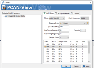
  •  This is my PCAN view config.

  • Can you upgrade your PCAN view application? I don't see any settings to set the sampling point here which is required. I am using PCAN view v5.1. PCAN-View: PEAK-System

  • This is PCAN Version 5.3.1 For the module name, there is no option other than CAN SJA 1000. Also, how to set the sample point using this version?

  • Under "Mode" in CAN setup you should be able to see CAN / ISO CAN option and it will have menu to configure bit rate and sampling point.