This thread has been locked.

If you have a related question, please click the "Ask a related question" button in the top right corner. The newly created question will be automatically linked to this question.

MSPM0G1105: Regarding the oscillation of an external ceramic resonator

Part Number: MSPM0G1105
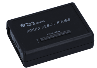
Other Parts Discussed in Thread: SYSCONFIG, TMDSEMU110-U, LP-MSPM0G3507

Tool/software:

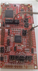
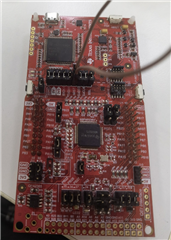
 I have started debugging a prototype.

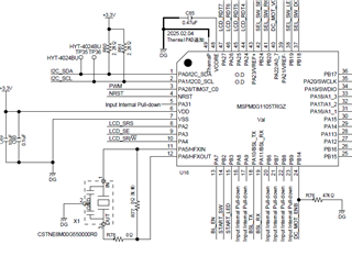
I have connected a ceramic resonator made by Murata Manufacturing to the outside.

The program has not been installed yet, and the power is only turned on, but it does not oscillate.

The product name is "CSTNE8M00G550000R0".

The Seiko Epson product introduced in the forum is difficult to purchase, so I chose the Murata product.

There is no matching information with MSPM0G1105, but it matches the MSP430F series and TMS320F series,

so I used it thinking it would be fine.

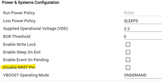
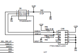
In my understanding, in order to oscillate with a ceramic resonator, the corresponding terminals must be assigned to HFXIN and HFXOUT.

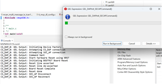
(Manual setting using XDS110, program installation, etc.)

Is this thinking correct?

Thank you in advance.

Hiroshi Yamada

  • Hi,

    I think it should be fine for the M0G1105 work with this ceramic resonator. And you can connect it through HFXIN and HFXOUT pins. Is there any issue you are encounter with on your board?

    Best regards,

    Cash Hao

  • Hi Cash

    Thank you for your quick reply.

    I was relieved to hear your comment that there is no problem with the ceramic resonator I selected.

    One more thing to confirm is that this ceramic resonator will not oscillate if you simply power on the

    MSPM0G1105 without a program, is that correct?

    I assume that it will not oscillate because it is not assigned to the HFXIN and HFXOUT pins, is that correct?

    Best regards,

    Hiroshi Yamada

  • Hi,

    This resonator looks fine on my side.

    You need to program the MCU with the HFXT configuration in the software. And also the hardware connection is correct. Then the resonator should work as expected when you power up the MCU.

    Best regards,

    Cash Hao

  • Hi Cash,

    Thank you again for your prompt comment.

    I'm relieved to know that my understanding was correct.

    Thank you very much.

    Hiroshi Yamada

  • Hi Cash,

    Today, I loaded an MCU program and checked it, and the ceramic resonator output was about 8 MHz.

    The voltage was only just under 400 mV.

    I checked the MCU standards but did not understand the required specifications.

    Currently, when I re-boot by resetting after programming the MCU, an error occurs where the XDS110 probe cannot connect to the target,

    and I think this is caused by the output level of the ceramic resonator.

    I would appreciate some advice.

    I'm in a hurry.

    Best regards;

    Hiroshi Yamada

  • Hi,

    The voltage 400mV seems low. Do you have any load caps around the HFXT in the circuit. If so, try remove those caps, since the built in load capacitance is high enough. 

    Best regards,

    Cash Hao

  • Hi Cash,

    Thank you for your quick comment.

    Is it really low?

    The current circuit diagram is as shown below, and there is no load.

    R77 is non-mount.

    How many volts do I need?

    I can't connect the XDS110 probe, so I can't switch the internal oscillator.

    Best regards;

    Hiroshi Yamada

  • Hi,

    To reconnect with MCU. You can try hold the NRST pin to low before power up the MCU. Hold it then power up the MCU. Then try to connect with XDS-110 and check if you can program the MCU or run a factory reset.

    For the crystal, I think the voltage should close to VDD. 

    Maybe you can try with R77 as 1Mohm and R78 as 330ohm, just like the one suggested in the crystal datasheet. 

    Best regards,

    Cash Hao

  • Hi Cash,

    Thank you again for your prompt comment.

    Unfortunately, changing the resistance value did not change the voltage level.

    Initializing the factory settings still doesn't work.

    I read an article on the Internet that said that increasing the load capacitance increases the excitation level,

    so I'm trying to try that, but the modification is difficult and I haven't been able to check it yet.

    Best regards;

    Hiroshi Yamada

  • Hi,

    Okay. Any progress on adding the load capacitance?

    However, if you still can not connect to the MCU somehow, it could also cause issues. Do you know how to run a factory reset on the MCU right?

    Best regards,

    Cash Hao

  • Hi Cash,

    Thank you for your comment.

    Changing the capacity is difficult, so I am still considering it.

    The aim of this attempt at changing the capacity is to change it to the initial setting (using the MCU's built-in clock),

    so I just want to connect the XDS110 probe, even if it is unstable.

    As you say, I just want to be able to reset it to the factory settings.

    I haven't yet figured out how to reset it to the factory settings, so please tell me.

    That's what I would like to know.

    Best regards;

    Hiroshi Yamada

  • Hi Cash,

    I have a question.

    >To reconnect with MCU. You can try hold the NRST pin to low before power up the MCU. Hold it then power up the MCU. Then try to connect with XDS-110 and check if you can program the MCU or run a factory reset.

    Does this mean that the NRST pin of only the MCU is held low?

    Currently, NRST is also connected to the connector for connecting the XDS110 probe.

    Does this mean that if it is only the MCU's NRSRT, work is required to separate it?

    You said to turn on the MCU's power while holding the MCU's NRST low, but can I release the low NRST after turning on the power?

    NRST is also connected to the XDS110 probe, but if I turn on the MCU's power while holding it low, and then release NRST and try to connect the XDS110 probe, I cannot connect. (Target not connect)

    Please let me know about your previous inquiry as well.

    Best regards;

    Hiroshi Yamada

  • Hi,

    You can disconnect the NRST pin to the XDS110 before powering up the MCU. After power up the MCU, you can release the NRST pin to HIGH. 

    For factory reset process, please refer to this guide. 

    3542.Factory_reset_v3.pdf

    Best regards,

    Cash Hao

  • Hi Cash,

    Thank you for your reply.

    I will check the guide for the factory reset process.

    I'm sorry for asking multiple times.

    >You can disconnect the NRST pin to the XDS110 before powering up the MCU. After power up the MCU, you can release the NRST pin to HIGH. 

    What does this mean?

    Is it the following part of Sysconfig?

    Or is it a setting on the XDS110 probe side?

    Please help.

    Hiroshi Yamada

  • Hi,

    No, it is not a configuration in sysconfig. 

    You can disconnect the NRST pin to the XDS110 before powering up the MCU manually on the hardware side. 

    After power up the MCU, you can release the NRST pin to HIGH by reconnecting the NRST pin to the XDS110 RST pin. 

    Best regards,

    Cash Hao

  • Hi Cash,

    Thank you for your quick reply.

    I'm really sorry for asking so many times.

    Is it perhaps something written in 3.7.3.1 of the XD110 probe user's guide?

    Is that right?

    Or do you mean not to connect the XDS110 probe before powering on the MCU, but to connect the XDS110 probe after powering on?

    Best regards;

    Hiroshi Yamada

  • Hi,

    It is not the thing written in the XD110 probe user's guide. Use LP for example, before power up the MCU, I remove the jumper on the NRST pin. It disconnect the conection between MCU and XDS-110 on the NRST pin. Then I manually connect the NRST pin to GND. And then power the board. 

    After power up the board, you can connect NRST back to the XDS-110 NRST pin. 

    Best regards,

    Cash Hao

  • Hi Cash,

    Thank you for your explanation so many times.

    In terms of hardware connection, does that mean that NRST must be separated between the XDS110 and the target MCU?

    To be precise, what I'm using now is the TMDSEMU110-U.

    If I try to implement the method you explained, I will need to modify the target board, right?

    I have also purchased the LP-MSPM0G3507, so I don't think any modifications will be necessary,

    but I need to consider how to connect it to my current target board and the 10-pin connector with SWD.

    Is this the right idea?

    Best regards;

    Hiroshi Yamada

  • Hi,

    In terms of hardware connection, does that mean that NRST must be separated between the XDS110 and the target MCU?

    I am not understanding this statement. All the connections between the XDS110 and target MCU are separated. You need to connect the SWD interface through a cable or a jumping wire between the XDS110 and MCU. So, they are all separated.

    I do not think you need to modify the board.  Okay, you do not reserve the NRST pin below. So it is hard for you to connect NRST pin to XDS110. That is fine, it is not necessary require to connect it back to XDS110. When you run the factory process, you can manually press the RST button instead of connecting the NRST pin to XDS110.  

    Best regards,

    Cash hao

  • Hi Cash,

    Thank you for your comment.

    I may be misinterpreting this, but I previously attached a circuit diagram which has a switch (tactile switch) that manually sets NRST to low.

    BThis switch is connected to NRST of CN5, which connects to the MCU and the 10-pin adapter of the XDS110 probe.

    Best regards;

    Hiroshi Yamada

  • Hi,

    The schematic looks fine. You do not need to connect RST pin to XDS-110 to run factory reset. 

    When you run the factory reset command without connect the RST pin, you will enter status. When you see this, you can manually press the button on your board. And it will automatically finish the factory reset command.

    Best regards,

    Cash Hao

  • Hi Cash,

    Thank you for letting me know.

    Thank you so much for your help so many times.

    Since the XDS-110 does not require RST, I need to cut the RST pattern connected to the 10-pin connector of the XDS-110 on the target board, right?

    I cannot check today, so I will check soon and get back to you.

    Best regards;

    Hiroshi Yamada

  • Hi Cash,

    It's been a while.

    I have other problems so I haven't tried it yet.

    This PCB needs to be restored so I will do so as soon as the other problems are resolved.

    I will be sure to let you know the results.

    Best regards,

    Hiroshi Yamada

  • Hi Hiroshi,

    Get it. When you have updates, could you start a new thread and @me in the post? We have rules that the threads need to be closed in one month.

    Best regards,

    Cash Hao