This thread has been locked.

If you have a related question, please click the "Ask a related question" button in the top right corner. The newly created question will be automatically linked to this question.

MSPM0G3519: Facing Issue to GPIO Read,

Part Number: MSPM0G3519

Tool/software:

Hi,

I am facing issue to read the GPIO,  Same circuit working with NXP Microcontroller. 

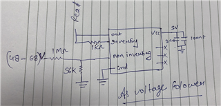
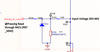
There is a voltage divider circuit. Voltage getting drop completely after divider. 

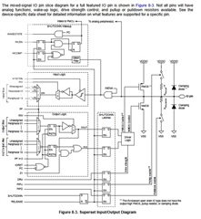
Cold you please clarify that the minimum current requirement of  SDIO  PINs of microcontroller. 

What I did:-

1)  Disconnect  R138 Series resistance from MCU,  Then voltage properly getting

  • Hi,
    The input level is purely voltage-driven. As long as you meet the required voltage, it should be able to read it.
    Best Regards,
    Diego Abad

  • Hi Diego,

    Could you please suggest the recommended GPIO settings for this.

    Currently we are using GPIO as Input with no internal pull-up/pull-down enabled.

  • Hi,
    You wouldn't usually need any particular configuration for this. You can try our input examples in the M0 SDK. It may be worth trying both pull-ups and pull-downs if they help your application. Monitoring the voltage levels using an oscilloscope could help.
    Best Regards,
    Diego Abad

  • Hi,

    We are reading a GPIO as input, through the API 

    DL_GPIO_initDigitalInputFeatures(config->pinPortIdx,config->gpioInversion, DL_GPIO_RESISTOR_PULL_UP, config->gpioHysteresis,config->gpioWakeup);

    As shown above there is a voltage divider before the GPIO(PB7_SDIO), when initialised the GPIO doesn’t read a HIGH input since the voltage is getting drained which we suspected was due to MCU, which we verified by using an OP-AMP in voltage follower mode of the divider as input to the GPIO and observed current of 70 mA.

    When uninitialized the GPIO reads HIGH as expected. Also, when initialized the GPIO has a current draw of 70 mA which is much higher than expected.

    As this Is highly unexpected behaviour. since the pin should get damaged due to such a high current. The maximum current on a SDIO is only 6mA

  • It looks like you are actually setting the GPIO to a low *output* somewhere. The pullups are pretty weak and can't draw 70 mA.

    What voltage do you expect on the pin? Note these are 3.3 V parts and any voltage above 3.5 or so will draw a lot of current through the ESD diodes.

    How the heck do you draw 70mA through a 100 ohm resistor? That implies a source voltage of 7 V with a direct short.

  • Here is the input output diagram. When set to an input it should be hi-z.