This thread has been locked.

If you have a related question, please click the "Ask a related question" button in the top right corner. The newly created question will be automatically linked to this question.

AM2634: On the TDCO configuration of the CAN secondary sampling points

Part Number: AM2634

Tool/software:

There are several problems in the configuration of CAN sampling points, which I would like to confirm:

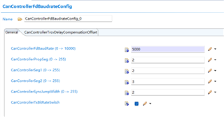
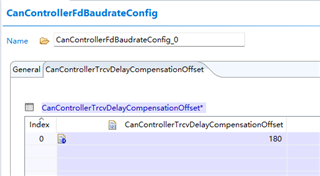
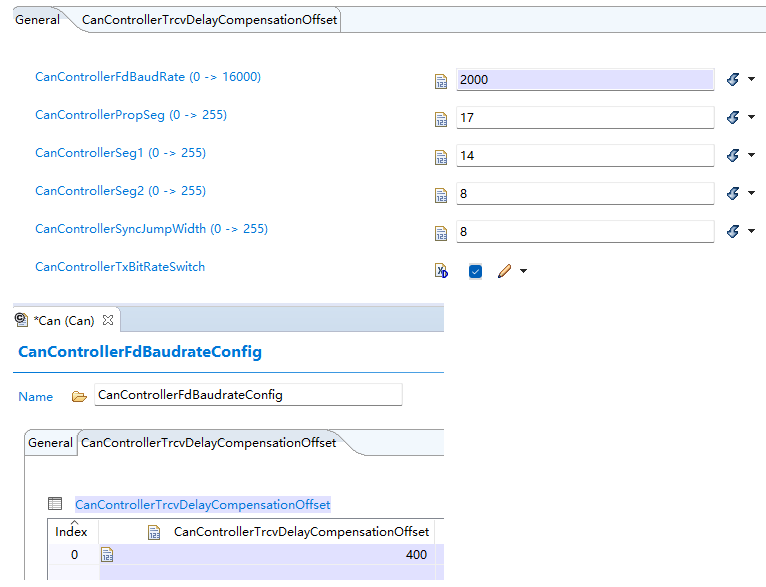
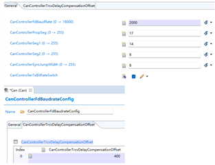
1. The sampling point data segment configuration requirement of CANFD is 80% of the sampling points. In the following figure, are the configuration parameters that the total number of TQS is 40 and the TDCO is 400 correct? What are the recommended configurations?

2. Why the configuration in EB, such as the above configuration, can only configure 400 at most, doesn't that mean that only 80% (400/500) sampling points can be configured.

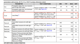
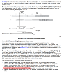
3.The description of the secondary sampling points in the manual is shown in the figure, whether it can be understood that the secondary sampling points are divided into two parts: the Delay Counter of automatic measurement and the TDCO in our EB configuration. Does the auto-measure part enable the SSP as soon as it is enabled?

4.Is there a way to test the configured TDCO? What is the impact if the TDCO in the first question is configured to 200?

  • Hi,

    Can i understand that what is the sampling rate you needed?
    And also are you using nominal baud rate or standard baud rate?

    So that i can come back with the above questions.

    Thanks,

    Mudit Bhansali 

  • Hi,

    1.The sampling point(SP) needs 80%

    2.The second sampling point (SSP) also needs 80%

    3.CAN FD data section baud rate needs 2M bps, arbitration section baud rate needs 500k 

  • Hi,

    Can you check out our default configuration, i already have this right.

    Thanks,

    Mudit Bhansali

  • Hi,

    The EB's default configuration is shown in Figure:

    CanControllerFdBaudRate:5000

    CanControllerPropSeg:2

    CanControllerSeg1:2

    CanControllerSeg2:3

    CanControllerSyncJumpWidth:2

    CanControllerTxBitRateSwitch :Enable

    CanControllerTrcvDelayCompensationOffset:180

    1.You mean that the TDCO is 180 also fits the configuration?

    CanControllerFdBaudRate:2000

    CanControllerPropSeg:17

    CanControllerSeg1:14

    CanControllerSeg2:8

    CanControllerSyncJumpWidth:8

    CanControllerTxBitRateSwitch :Enable

    CanControllerTrcvDelayCompensationOffset:180

    2.You mean TDCO is 180 fits SSP=80%, So is 100 or 400 right ?

    3. Is there a calculation method for TDCO and SSP? For example, if SSP=80%, then TDCO= (CanControllerPropSeg+CanControllerSeg1+CanControllerSeg2+1) *80%. I want to know the relationship.

    Thanks,

  • Hi,

        CanConfigSet_CanController_0_CanControllerBaudrateConfig_0 =
    {
        1000U,      /* in Kbps */
        20U,       /* Prop Segement value */
        14U,          /* Phase Segment 1 */
        5U,          /* Phase Segment 2 */
        1U, /* Sync jump width */
        40U, /* Sum of all timing parameters */
        2U,   /* Controller BRP value for Baud */
    	 /* Data phase Baudrate */
        {
            5000U,     /* in Kbps */
            3U,        /* Prop Segement value */
            3U,           /* Phase Segment 1 */
            1U,           /* Phase Segment 2 */
            1U,  /* Sync jump width */
            8U, /* Sum of all timing parameters */
            2U,   /* Controller BRP value for Baud */
            14U, /* Specifies the Transceiver Delay Compensation Offset */
            (boolean)TRUE, /* Specifies if the bit rate switching shall be used */
        }
    };

    In the above MCAL config, lets understand the calculation:

    bit rate(bits per second) = (CAN clock in Hz) / BRP / (1 + TSEG1 + TSEG2)

    where:

    CAN clock is functional clock of CAN module (80MHz)

    BRP: Bit rate pre-scalar value

    TSEG1, TSEG2: Time segments used to define sampling point for the bit.

    TSEG1: Time before the sampling point = Prop_Seg + Phase_Seg1

    TSEG2: Time after the sampling point = Phase_Seg2

    In this configuration calculating the Bit rate: Nominal

    TSEG1= 20+14=34
    TSEG2=5
    BRP=2
    Nominal Bit rate = 80Mhz / (2*(34+5+1)) = 1Mbps

    In this configuration calculating the Bit rate: Data

    TSEG1= 3+3=6
    TSEG2=1
    BRP=2
    Data Bit rate = 80Mhz / (2*(6+1+1)) = 5Mbps

    Sampling formula: Sampling Point(%) = (1 + TSEG1) / (1 + TSEG1 + TSEG2), Typical value of sampling point is between 75-90%.
    There is no relation between sampling (%) and TDCO.

    Hope this calculation will help.

    Thanks,
    Mudit Bhansali

  • Hi,

    I already know how to calculate SP,For the calculation method of SSP and TDCO still don't quite understand,Can you give an example as you explained SP.

    Thanks,

  • Yes, there is a relation between `trcvDelayCompensationOffset` and the Secondary Sample Point (SSP) percentage.

    The `trcvDelayCompensationOffset` is a parameter used in CAN FD to compensate for the delay introduced by the transceiver. This delay can affect the timing of the sample points, including the SSP.

    The `trcvDelayCompensationOffset` is typically used to adjust the SSP location to ensure that it falls within the desired range. The SSP percentage is usually calculated based on the bit time, and the `trcvDelayCompensationOffset` is used to fine-tune this calculation.

    Thanks,
    Mudit Bhansali

  • In order to get the required SSP(%) , we can adjust the SSP location with the use of trcvDelayCompensationOffset.

    SSP Percentage = ((SS + PS1 + (PS2 x (1 - (SSP Location / Bit Time)))) / Bit Time) x 100
    where,

    - SSP Location
     is the location of the secondary sample point in time, typically measured in nanoseconds (ns) or microseconds (us).

    - Bit Time is the total time for one bit, typically measured in nanoseconds (ns) or microseconds (us).

     In general, the trcvDelayCompensationOffset is used to adjust the SSP location to compensate for the transceiver delay. A positive trcvDelayCompensationOffset value will move the SSP to the right (i.e., later in the bit time), while a negative value will move it to the left (i.e., earlier in the bit time).

    ex:

    // Calculate the SSP location without compensation
    uint32_t sspLocation = (bitTime * sspPercentage) / 100;
    
    // Calculate the SSP location with compensation
    uint32_t compensatedSspLocation = sspLocation + trcvDelayCompensationOffset;
    
    // Calculate the new SSP percentage with compensation
    uint32_t compensatedSspPercentage = (compensatedSspLocation * 100) / bitTime;


    For more details refer TRM: https://www.ti.com/lit/ug/spruj55b/spruj55b.pdf?ts=1742375150848&ref_url=https%253A%252F%252Fwww.google.com%252F

    Thanks,
    Mudit Bhansali

  • Hi,

    1.Through calculation method of the EX, we can through the parameter as shown in figure calculated sspLocation, but we still can't confirm trcvDelayCompensationOffset parameters configured to how much is appropriate. Can you give us an appropriate parameter in the figure and explain why?

    In addition, the Can transceiver we used is TCAN1145.

    2.According to the information you gave, can I understand that the value of TDCO  can be set as the LOOP DELAY parameter of TCAN1145 (215 or 225ns), as shown in the following figure?

    3.If the second is true, can we understand that when sspPercentage is 80%, sspLocation=400ns, The compensatedSspLocation should be equal to sspLocation + trcvDelayCompensationOffset = 400 ns + LOOP DELAY = 400 ns + 215 ns. So compensatedSspLocation is 615ns.

    We assume sspPercentage is 100%, So compensatedSspLocation is 500ns+215ns, and the maximum compensatedSspLocation can only be 715ns.

    So why is sspPercentage 80%, TDCO is set to 400ns, compensatedSspLocation is 400ns+400ns > 715ns can still collect CAN data normally instead of displaying an error frame.

    Thanks,

  • 1.Through calculation method of the EX, we can through the parameter as shown in figure calculated sspLocation, but we still can't confirm trcvDelayCompensationOffset parameters configured to how much is appropriate. Can you give us an appropriate parameter in the figure and explain why?

    It is recommended to set the TDCO and TDCF to the equivalent amount of time as the DTSEG1. You need to convert the tq of the DTSEG1 register into an equivalent mtq based on the DBRP used.

    In your example, the DBRP=5 (400MHz/80MHz), 1tq=5mtq --> TDCO = 5*(17+14)=155mtq

  • Hi,

    Through your description, can I understand that:

    DBRP=MCU Clock/ MCAN Clock

    TDCO= DBRP* TSEG1=DBRP* (Prop_Seg + Phase_Seg1)

    Thanks,

  • 2.According to the information you gave, can I understand that the value of TDCO  can be set as the LOOP DELAY parameter of TCAN1145 (215 or 225ns), as shown in the following figure?

    The Transmitter Delay Compensation consists of two different delay values. The first delay value is the actual transmitter loop delay and is measured by the device on each transmitted CAN FD frame at the falling edge of the FDF bit to the res bit. The second delay is set by the TDCO mtq configured in the register value.The actual Transmitter Delay Compensation Value (TDCV) is the sum of the loop delay and the TDCO.

    The LOOP DELAY (215ns or 225ns in TCAN1145 DS) doesn't include the cable delay. 

  • Hi Xinlei,

    The DBRP defines the length of the time quantum (the basic time unit of the bit time), and the bit timing logic (SEG1, SEG2, SJW) defines the number of time quanta in the bit time. Bit time (ns) is 1000 / baudrate(mbps).

    The MCAN functional clock source can be SYS_CLK, XTALCLK, etc. 

    The clock source is selected by MSS_RCM_MSS_MCAN0_CLK_SRC_SEL

    For example, MCAN FCLK = SYS_CLK / CAN_CLKDIV_SEL Bit

  • tq = CAN#_CLK / DBRP

    bit time = (SEG1 + SEG2 + 1 (Sync) ) * tq

  • Hi,

    According to what you said 1tq=5mtq,TDCO = 5*(17+14)=155mtq,Can I say that TDCO is equal to (CanControllerPropSeg +CanControllerSeg1)*tq

  • Can I say that TDCO is equal to (CanControllerPropSeg +CanControllerSeg1)*tq

    Yes, you are correct. The unit of TDCO is mtq. TDCO =  (CanControllerPropSeg +CanControllerSeg1)*tq / mtq

  • Hi,

    I'm going to double-check that the value that TDCO needs to fill in for EB is 387.5ns .TDCO = 5*(17+14)=155mtq=155*2.5ns=387.5ns

  • Let's know your test result after you finish your test. Thanks

  • Hi,

    What I mean is, if measured in nanoseconds, according to the calculation method you mentioned, would the value of TDCO be 387.5ns?

    Thanks,

  • Yes, you can correct.