This thread has been locked.

If you have a related question, please click the "Ask a related question" button in the top right corner. The newly created question will be automatically linked to this question.

TM4C129XNCZAD: Boot loader

Part Number: TM4C129XNCZAD
Other Parts Discussed in Thread: TEST2

Tool/software:

Dear Sir,

We used Ti based flash based booloader  exmplae. We have modified the bl_config.h for UART based interface update.

It is working also. We used UART1 ,baud rate 115200 and LM flash loader to update the application.

Now question is that if we interrupt the process of LM flash loader update  in between then not able to update again.

and device also not bootup after restart.

What more setting to be do in bl_config.h  like CRC check etc. To avoid this condition.

CRC_Check is sufficient to make device retain old code.

0525.bl_config.h

  • Now question is that if we interrupt the process of LM flash loader update  in between then not able to update again.

    and device also not bootup after restart.

    If you interrupt in the  middle then your firmware is only partially programmed. The address at 0x0 and 0x4 will have a valid SP and Reset vector. After power up, the processor thinks that there is a valid firmware by checking the SP and Reset vector and jumps to the application despite the firmware image is incomplete. 

    What more setting to be do in bl_config.h  like CRC check etc. To avoid this condition.

    CRC_Check is sufficient to make device retain old code.

    Yes, use the CRC_Check so that bootloader will check for a complete firmware image by verifying the CRC before jumping to the application or otherwise enter the bootloader mode. 

  • Dear Sir,

    so in bl_config.h make  enable #define CRC_Check is sufficient or anything also require like  #define ENFORCE_CRC  or  //#define ENABLE_BL_UPDATE . Please confirm 

    We have attached  bin file before and after binpack.

    Before -MT30s_FW_14_11.bin  

    After test2.bin

    I enable check_ crc and enforce_ crc  alongwith existing uart update alreaay mentioned in earlier post in bl_config.h

    but device is not booting . Is any thing else require?

    8231.MT30s_FW_14_11.zip8231.test2.zip2845.bl_config.h

  • Hi,

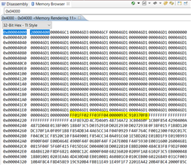
      Can you please refer to this post? Can you check in the memory window if the length and CRC value are there at the end of the vector table? After the binpack, this is what you are supposed to see the marker words, length and CRC relative to the application image starting at 0x4000. 

    https://e2e.ti.com/support/microcontrollers/arm-based-microcontrollers-group/arm-based-microcontrollers/f/arm-based-microcontrollers-forum/1434578/tm4c1294ncpdt-bootloader-crc32/5501080?tisearch=e2e-sitesearch&keymatch=binpack#5501080

  • Dear Sir,

    As per spmu301e .pdf  the marker1,marker2 ,crc length,crc  and remaining 4 word to be defined above vector table. We did the same and already shared my bin file before and afet bin pack. I  am using keil compiler. The bin file genrated by keil complier  by defining the marker1,2 ,length,crc  then also it is not booting. Above image and post not clear to me .Can you see my bin file and elaborate reason

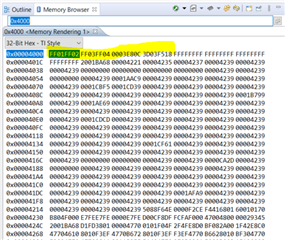
  • Please look at my screenshot vs yours shown below. My marker words, length and CRC starts at 0x4208. Yours starts at 0x4000 which is opposite.

  • As you commented that  my bin file data showing on location 0x4000 onward (Marker 1 ,Marker 2  ,length,CRC) . When i open my bin file on on line bin editor it show @0x0000 location . So i am confused that how to view. We don't have memory browser. 

    As per document macro Check_CRC ,it state that marker and crc insert at top of the vector table and your screenshot show below vector table. One more thing that binpack.exe also adding crc at top of the table only.

  • First of all, your original MT30s_FW_14_11 before binpack.exe must be built to start at 0x4000 as this is where the bootloader expects it to be according to your bl_config.h. Did you do that?

    So i am confused that how to view. We don't have memory browser. 

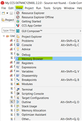
    What do you mean you don't have memory browser? Don't have use CCS or any type of IDE? In CCS, go to View->Memory Browser, see below. If you are using a different IDE then you need to find out how to open a memory window.

    As per document macro Check_CRC ,it state that marker and crc insert at top of the vector table and your screenshot show below vector table. One more thing that binpack.exe also adding crc at top of the table only.

    I think the document is a bit confusing depending on where you reference as the top. If you look at the vector table, the first location at 0x0 is the Stack Pointer and the second location at 0x4 is the reset vector. This is actually the bottom of the vector table. You cannot have the marker at 0x0 and 0x4. The top of the vector table means the end of the table at the highest address of the vector table.