This thread has been locked.

If you have a related question, please click the "Ask a related question" button in the top right corner. The newly created question will be automatically linked to this question.

AM2434: Software reset

Part Number: AM2434
Other Parts Discussed in Thread: SYSCONFIG

Tool/software:

Hello experts,

I need to perform a chip reset whenever a certain string is received from the UART.

The function SOC_generateSwWarmResetMainDomain() is called after receiving the specific message, the firmware execution stops, but never restarts.

Am I missing something?

Best Regards,

Andrea

  • Hello Andrea,

    I am looking at your queries and you may expect reply in one or two days .

    Regards,

    Anil.

  • Hello Andrea,

    The above API should work and it does the SOC Resets.

    Can you please share a code snippet or project of how you are doing the above implementation in your project ?

    Regards,

    Anil.

  • Hello Anil,

    I'm sending you the project.

    uart_reset.zip

    The reset API is called after the message 01 10 00 00 00 02 04 00 00 00 01 32 6F (HEX) is received on the UART: CONFIG_UART0_RS485.

    void modbus_writeDoubleWord(modbusReg_struct *regType)
    {
        switch(regType->regPointer)
        {
        case 0:
            if (regType->value == 1)
                regType->resetDrive = 1;
            break;
    
        default:
            regType->error = C_MODBUS_ERROR_REGISTER_UNDEFINED;
            break;
        }
    }

    After receiving the message the flag "regType->resetDrive" is set to 1 (line 7)

    //Reset driver if requested
    if(regType.resetDrive)
    {
        //Wait for trasmit to finish
        while(uartType->txBusy)
        {
            shs_UART_trasmit_check_done(uartType);
        }
        //Reset MCU
        SOC_generateSwWarmResetMainDomain();    //TODO: Verificare reset
    }

    The function "modbus_detect" checks the value of  "regType->resetDrive" and calls "SOC_generateSwWarmResetMainDomain();".

    The bootmode is set to OSPI mode and the fimrware is located in an OSPI flash.

    The goal is to start executing the firmware inside the flash after a reset.

    BR,

    Andrea

  • Hello Andrea,

    Thanks for sharing the above details .

    I can look at your code and will come back soon .

    Regards,

    Anil.

  • Hello Andrea,

    Can you please confirm whether the control is going to the 10th line of the above code or not ?

    If the control goes to the 10th line, then the SOC will go through the Reset.

    After the Reset, the SOC boot flow starts from the RBL → SBL OSPI →Application.

    Again, the application starts freshly. Currently, I suspect that your code is really the control that goes to the 10th line or not.

    Are you using XIP mode ? The SBL always picks an application image from the external flash and will put it into the DDR/MSRAM memory. So, when you are using the XIP mode, you need to keep the code in FLASH rather than the RAM memory.

    Please follow steps below if you are using the XIP mode .

    https://software-dl.ti.com/mcu-plus-sdk/esd/AM243X/10_01_00_32/exports/docs/api_guide_am243x/BOOTFLOW_XIP.html

    Regards,

    Anil.

  • Hello Anil,

    I'm using the appimage.hs_fs file; do I need to switch to XIP mode?

    "Can you please confirm whether the control is going to the 10th line of the above code or not ?"

    Yes, line 10 of the code gets executed and the program gets stuck when line 746 of soc.c is being executed:

    If I try to pause the debug after exeuting this function the program stops at F10801C0

    Kind Regards,

    Andrea

  • Hello Andrea,

    Can you please share the UART log ?

    I feel that the SOC is resetting.

    And, I assume that you are expecting the CCS to run from your code freshly and this will not happen because when you load an example from the CCS, the CCS will directly write the data on the MSRAM/DDR location and, after the reset, the content will be lost and the code will not execute from the Application.

    You can simply confirm whether the SOC is going through the Reset or not. Just check the UART log which prints SBL log for every reset and this confirms whether the SOC is resetting or not.

    Regards,

    Anil.

  • Hi,

    I just checked the UART log.

    BOOTMODE pins are set in a way that primary bootmode is OSPI and backup boot mode is UART.

    When I power up the board SBL manages to load the flash firmware using OSPI.

    LOG:

    DMSC Firmware Version 9.0.7--v09.00.07 (Kool Koala)
    DMSC Firmware revision 0x9
    DMSC ABI revision 3.1

    [BOOTLOADER_PROFILE] Boot Media : NOR SPI FLASH
    [BOOTLOADER_PROFILE] Boot Media Clock : 100.000 MHz
    [BOOTLOADER_PROFILE] Boot Image Size : 108 KB
    [BOOTLOADER_PROFILE] Cores present :
    r5f0-0
    [BOOTLOADER PROFILE] SYSFW init : 12183us
    [BOOTLOADER PROFILE] System_init : 5366309us
    [BOOTLOADER PROFILE] Drivers_open : 276us
    [BOOTLOADER PROFILE] Board_driversOpen : 73us
    [BOOTLOADER PROFILE] Sciclient Get Version : 9844us
    [BOOTLOADER PROFILE] CPU load : 180616us
    [BOOTLOADER_PROFILE] SBL Total Time Taken : 200596us

    Image loading done, switching to application ...

    I noticed that when a software reset is issued (SOC_generateSwWarmResetMainDomain) the IC enters the backup boot mode.

    LOG:

    02000000011a0000616d3634780000000000000048534653000002000000020002a6000000000000b018658ad99dc903c8c9bfb27b12751099920a042ad1dfea7b7ba57369f15546de285edde6a7b39a8bdc40a27b237f8fb1e57f245e80b929c1e28b024aa2ecc6ad0bc40b000000000000000000000000000000000000000000000000000000000000000000000000000000000000000000000000000000000000000000000000eabc453af992a159794c85bd6e515b28deeba13d30ecf9be0fbddcd2b7b5d000CCCCCCCC

    For some reason the SBL isn't able to load the firmware from the OSPI flash and uses the backup boot mode instead.

    BR,

    Andrea

  • Hello Andrea,

    Can you please confirm, did you change the SBL OSPI application or, by default, SBL OSPI is used in your application ?

    Regards,

    Anil.

  • Hello Anil,

    I'm using a custom SBL firmware edited starting from sbl_ospi example.

    BR,

    Andrea

  • Hello Andrea,

    My suggestion is that, use  the TI SBL and confirm whether this issue is still existing or not.

    This confirms your SBL creates an issue or an application creates an issue .

    Please  share the modified SBL changes as well to review the changes.

    Regards,

    Anil.

  • Hello Anil,

    After comparing the custom SBL project with TI's SBL ospi I can confirm that the only difference is the flash device being used; the board uses a different flash from the eval board.

    What I've tried:

    1) I tried adding a call to "loop_forever();" at the very first line of the main in the custom SBL project to debug it.

    /* call this API to stop the booting process and spin, do that you can connect
     * debugger, load symbols and then make the 'loop' variable as 0 to continue execution
     * with debugger connected.
     */
    void loop_forever(void)
    {
        volatile uint32_t loop = 1;
        while(loop)
            ;
    }
    
    int main(void)
    {
        int32_t status;
    
        loop_forever();
    
        Bootloader_profileReset();
    
        Bootloader_socWaitForFWBoot();
    

    At power up the entire program gets executed correctly and the main project is booted.

    After a "SOC_generateSwWarmResetMainDomain();" call from the main application the MCU enters backup boot mode without entering the custom SBL loaded in the flash.

    2) I tried adding a call to the functions

    Board_driversClose();
    Drivers_close();
    Board_deinit();
    System_deinit();

    right before "SOC_generateSwWarmResetMainDomain();" but nothing changed.

    BR,

    Andrea

  • Hello Andrea,

    My suggestion is that, use  the TI SBL and confirm whether this issue is still existing or not.

    This confirms your SBL creates an issue or an application creates an issue .

    Please do this step as well.This will give information about either the SBL is creates an issue or the Application .

    I am routing your query to an SBL expert.

    Typically, the boot flow goes back to back-up mode, which is not the correct way.

    Without knowing why SBL is going back to back up boot mode cloing the drivers may not help here.

    So, let the SBL expert comment on this issue.

    Please share the flash details using what protocol, like 8D 8D 8D or any other protocol or flash part number and syscfg which helps us to debug the issue on the flash side.

    Regards,

    Anil.

  • Hello Anil,

    after attempting with the TI SBL the reset works correctly: the board resets succesfully and the chip enters OSPI boot mode.

    Here's some details about the flash:

    - device: W25Q128JVSIM

    - protocol: 4S-4S-4S

    In the zip folder you can find the project of the custom sbl

    HT-NET_sbl_ospi.zip

    BR,

    Andrea

  • Hi Andrea, 

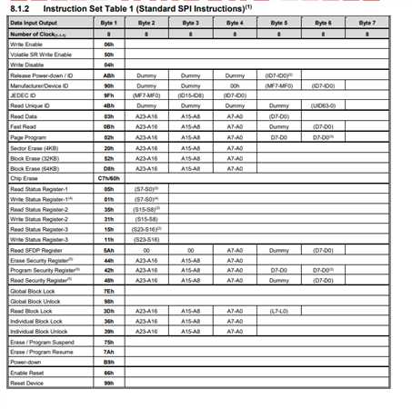
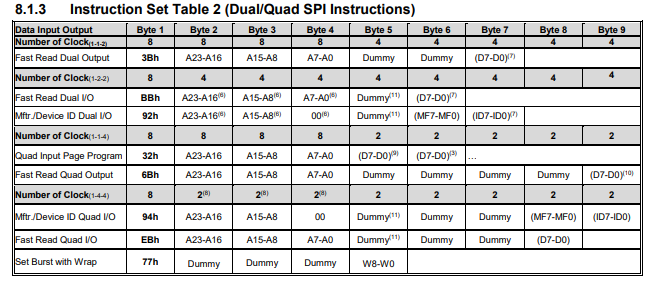
    Even before I go ahead and look at the code, I went straight to look at the Flash section in the sysconfig of the application you shared with me.

    I see you configured 4S-4S-4S mode, but when I see the data sheet, all I see is that 4S-4S-4S is not a mode the flash supports.

    Please find relevant snapshots from the datasheet.

    Best Regards,

    Vaibhav

  • Hello Vaibhav,

    I'm using QPI mode to enable 4s-4s-4s mode.

    I tested this setup using the ospi_flash_io example provided by TI and it works correctly.

    Best Regards,

    Andrea

  • Interesting looks like I referred a datasheet which is pretty close to the one which you are seeing.

    I referred the following datasheet: https://www.winbond.com/hq/product/code-storage-flash-memory/serial-nor-flash/?__locale=en&partNo=W25Q128JV

    If the setup worked with the OSPI flash IO, then the Flash and OSPI section is ruled out. Need to look at the code.

    I would give it a green sign from flash and OSPI perspective.

    Regards,

    Vaibhav

  • Hi Andrea,

    I am assuming this thread is not closed yet?

    Because it works with TI SBL OSPI and not your custom SBL OSPI?

    Regards,

    Vaibhav

  • Hi,

    that's correct, I'm trying to figure out what causes the custom SBL OSPI to not be working.

    BR,

    Andrea

  • Hi,

    I got a reference to this datasheet yesterday and saw that there is another table where it states about support of 4-4-4 protocol so its valid.

    that's correct, I'm trying to figure out what causes the custom SBL OSPI to not be working.

    I am also doing a diff between the default SBL OSPI and the one which you sent out. Please update me if you find something, I will do so the in the meantime as well.

    Regards,

    Vaibhav

  • Hello,

    In the zip folder you can find the project of the custom sbl

    HT-NET_sbl_ospi.zip

    I have a doubt here.

    You said this is custom SBL OSPI.

    But all I see is change in the OSPI and FLASH sections from SysConfig and the code in main,.c is same compared to what the default MCU PLUS SDK 9.00.00.35 has to offer.

    Am I missing something or you have made changes to source/drivers?

    Looking forward to your response.

    Regards,

    Vaibhav

  • Hi Andrea,

    I see you are missing this configuration in your project.

    And moreover, in the latest release of MCU PLUS SDK AM243, you would see an API is introduced which you are missing out on in 9.00.00.35.

    The API is: flashFixUpQspiBoot

    Please incorporate the latest changes and let me know if it works out for you.

    Regards,

    Vaibhav

  • Hello Vaibhav,

    I checked the API "flashFixUpQspiBoot" and noticed it uses an output pin to reset the flash IC.

    Unfortunatelly the custom board doesn't have a pin to reset the flash. I will try this change with the next revision of the custom board in the future.

    Thank you for the support,

    Best Regards,

    Andrea

  • Hi Andrea,

    Thanks for the heads up. I will be looking forward to enabling you on the next revision of the board.

    Please feel free to open new e2e to continue the discussion.

    Regards,

    Vaibhav