This thread has been locked.

If you have a related question, please click the "Ask a related question" button in the top right corner. The newly created question will be automatically linked to this question.

AM2634-Q1: Customer used AM2634 for HSM development issue?

Part Number: AM2634-Q1
Other Parts Discussed in Thread: AM2634

Tool/software:

Hi Experts,

Customer used AM2634 for HSM development. For boards in the same batch, some boards HSM services can be normal, while some boards HSM services are abnormal (3 failed/ 10 boards). Could you give us suggestion or debug guide? Thanks.

  • Hi,

    The error seems to be coming when efusing the SW rev version, as per the OTP KW documentation "Section 6 : Debugging"

    Was the SW rev efused earlier on these boards?

    Had you provided msv values to your certificate? I don't see that being written here either

    Could you share the full logs (i.e. including the parsing)?

    One way to check this would be to go via the multi-mode approach (i.e. program via multiple certificates) , as per OTP KW doc "Section 3 "

    Regards,

    Nikhil Dasan

  • Hi Nikhil,

    Could we support con-call with customer tomorrow?

  • OTP Keywriter version SR1.1_09.01.05.

  • as discussed, 
    Please share the below before the call

    1. SDK version,
    2. Were there retries of flashing the contents or did it not work in the first go..
    3. Full logs from the keywriter application for good scenario and bad scenario

    4. Did you use TI's certificate generation script to generate the keywriter certificate? If yes, could you share the commands and args used with the script?

    Regards,

    Nikhil

  • Adding to the above, please ensure the below as per datasheet

    Please share the screenshot of the probe output showing stable VPP for this case on the faulty boards

    Regards,

    Nikhil

  • Hi

    /cfs-file/__key/communityserver-discussions-components-files/908/sbl_5F00_keywriter.release.tiimage

    In the above script, i have used the below command to generate certificate on OTPKW 9.1 and SDK 9.1

    I have removed " --msv 0x1E22D --msv-protect  --sr-sbl 1 --sr-hsmRT 1 --sr-app 1" from the script for now. 

    Can you check with file? Please ensure you have a setup with keywriter logs coming as before.

    ./gen_keywr_cert.sh -t tifek/am263x/SR_11/ti_fek_public.pem -b keys_devel/bmpk.pem --bmek keys_devel/bmek.key -b-protect --bmek-protect -s keys_devel/smpk.pem --smek keys_devel/smek.key -s-protect --smek-protect --keycnt 2 --keycnt-protect --keyrev 1 -d am263x --devSrVer SR_11

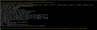
  •  The result is as follows. Is that right?

  • Information about the serial port after the key is regenerated and a new otpkeywriter is generated:

    Starting KeyWriter Bootloader ...

    [HSM_CLIENT] New Client Registered with Client Id = 0
    INFO: Bootloader_socLoadOTPHsmRtFw:62: Key Writer HSMRT Size in Bytes : 66036
    INFO: Bootloader_socLoadOTPHsmRtFw:63: Key Writer hsm runtime firmware load complete
    INFO: Bootloader_socLoadOTPHsmRtFw:64: Below Device DETECTED
    Device Type : HSFS
    SR version 1.1

    [HSM_CLIENT] New Client Registered with Client Id = 2
    [HSM CLIENT] OTP-KW 64bit version string = 0x001330100090100

    [HSM CLIENT] OTP-KW Information
    [Soc Type] = AM263x
    [Device Type] = HS-FS
    [HSM Type] = HSM_V1
    [Bin Type] = OTPKW
    [OTP-KW Version] = 9.1.0

    #
    # Validating certificate..
    #

    #
    # Decrypting extensions..
    #

    * MPK Options: 0x0

    * MEK Options: 0x0

    * MPK Opt P1 : 0x0

    * MPK Opt P2 : 0x0

    * MEK Opt : 0x0

    SMPKH extension disabled

    SMEK Hash extension disabled

    BMPKH extension disabled

    BMEK Hash extension disabled

    EXT OTP extension disabled

    MSV extension disabled


    SBL SW Rev extension disabled


    HSMRT SW Rev extension disabled


    * APP SWREV: 0x000000000000000000000001000000000000000000000001

    [u32] key_cnt : 0x303


    [u32] key_REV : 0x101

    #
    # Programming Keys..
    #

    SWREV APP:

    block: 1, row: 5 data: 0x0

    block: 1, row: 6 data: 0x0

    block: 1, row: 7 data: 0x1

    block: 1, row: 8 data: 0x0

    block: 1, row: 9 data: 0x0

    block: 1, row: 10 data: 0x1

    Efuse writing row failed

    Programmed 2/3 rows successfully

    [HSM CLIENT] OTP-KW Error encountered in OTP Keywriter

    [HSM CLIENT] OTP-KW debugResponse = 0x00a0d023
    [HSM CLIENT] OTP-KW Error phase = 0x3
    [HSM CLIENT] OTP-KW Error module = 0x02
    [HSM CLIENT] OTP-KW Error stage = 0x0d
    [HSM CLIENT] OTP-KW Error customer key extension = 0xa

    [BOOTLOADER_PROFILE] Boot Media : undefined
    [BOOTLOADER_PROFILE] Boot Image Size : 0 KB
    [BOOTLOADER_PROFILE] Cores present :
    [BOOTLOADER PROFILE] System_init : 26us
    [BOOTLOADER PROFILE] Drivers_open : 30

  • Hi,

    This is not from the binary I shared above right? as I had removed the swrev app from the build command.

    Also, before flashing anything else, can you share their schematics? i will have it checked with the HW folks if anything regarding VPP is missed

    Regards,

    Nikhil

  • Adding to the above, In the below document, can you check if they have provided the 0.1 uF capacitor?

    ti.com/lit/an/sprabj8c/sprabj8c.pdf

  • 1.VPP currently uses an external access 1.7V power supply with no 0.1 uF capacitor

    2.According to the manual, it can be provided to VPP with internal power supply. How should the circuit be adjusted?

  • Hi,

    According to the manual, it can be provided to VPP with internal power supply. How should the circuit be adjusted?

    As per the manual, the 0.1 uF capacitor is required when you are providing an external VPP supply. I believe this is the customer's current scenario right?

    Only on the AM263 CC, we populate the VPP supply on board. Are you asking how to do the below?

    And devices like AM263p and AM261 has  On-chip VPP supply.

    Regards,

    Nikhil Dasan

  • Note If 0.1u capacitor is added to the VPP, OtpkeyWriter fails to convert the HS mode

  • Could you please share your schematics for review?

    Regards,

    Nikhil

  • Which circuits are needed?

  • Hi,

    Please share the VPP circuits

    Regards,

    Nikhil

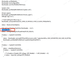
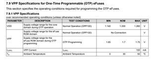
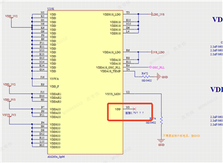
  •  VPP External 1.7V power supply Add 0.1u capacitor to the PCB, and the OtpkeyWriter fails

  • Hi Nikhil,

    Could you speed up this issue? Or could you verify the same SDK version and OTP key writer based on our AM263x-CC board, and then share the step by step guide to us? Thanks.  

  • Hi Nikhil,

    I have sent the calendar to you, and then we can discuss this issue here. Thanks.

  • As discussed in the call, copying the latest content of mail here

    • Share the detailed timing about power up sequence to customer by COB, today.
      • Shiv shared this via mail 
    • Confirm external hardware design schematic and others customer how to design VPP 1.7V by COB, today.
      • Shiv: Yes we have tried that flow using external supply without SW control no problem with that.

        Please let us know how Megmeet is programming the OTPs like they are using JTAG, CCS or UART etc.

    Regards,

    Nikhil Dasan

  • Hi Nikhil,

    I have just successfully converted the SE mode with the OTP key writer generated by myself, and the process should be fine.
    The original conversion failure process is as follows:
    1. Burn the OTP key writer program, power it on, and check whether serial port data can be accepted. In this case, the VPP is not connected to the 1.7V power supply.
    2. Turn off the PCB auxiliary power supply, connect the VPP to 1.7V power supply, and turn on the PCB auxiliary power supply. After receiving data from the serial port, the SE mode fails to be converted.

  • As suggested in the call.

    Customer should not keep the VPP ON and then restart the board.

    They have to turn on VPP after Power ON of the board (i.e. VDD) and before the application starts.

    This is difficult in qspi boot mode, as there is no control in execution from power ON to KW Application start. Hence an LDO is a must in this boot flow.

    Alternatively, the boot mode such as UART and JTAG, has full control of loading the application from power ON, (i.e. After power ON, user can load application manually). Only in this case, the external VPP is suggested as the sequence could be followed here.

    As part of suggestion, TI asked the customer to keep while loop in the main function of the KW Application, so that once it is loaded, the application is not executed. So that customer would have time to power ON the VPP and then using CCS, exit the while loop and run the application. 

    This is not tried at TI's end, and something that Customer can try at their end. But the suggestion from TI would still be to either use LDO in qspi mode or use UART mode to do OTP KW.

    Regards,

    Nikhil Dasan

  • Hi Nikhil,

    I tried the following:
    1. Add the ClockP_sleep() function before the main loop starts The VPP1.7V conversion failed to be connected during the delayed wait.
    2. Also try the keywriter_setVpp() function After adding ClockP_sleep(), the conversion fails when VPP1.7V is connected with delayed wait.
    Any other suggestions?

  • Hi,

    Add the ClockP_sleep() function before the main loop starts The VPP1.7V conversion failed to be connected during the delayed wait.

    When did you switch ON VPP in this case? Was it on before the board is reset or did you switch on the VPP during this 5 sec delay?

    Also try the keywriter_setVpp() function After adding ClockP_sleep(), the conversion fails when VPP1.7V is connected with delayed wait.

    The Keywriter_setVpp() API is only useful if you have a LDO in the path. Else, this API does not do anything apart from Configuring the LDO. Have you integrated the LDO and then used this API?

    Any other suggestions?

    If the above does not work, then the only suggestion from TI is to either use a LDO which is controlled by GPIO from software (similar to CC) or use UART to load the KW application as demonstrated by TI in the call.

    Regards,

    Nikhil Dasan

  • hi,

    Both tests turn on VPP with a 5 second delay. We want to add GPIO control to turn on VPP, but how do we import the sbl_keywriter routine into CCS and compile it?

  • Hi,

    In the OTP KW package, we can find the file syscfg_c.rov.xs below

    Can you confirm if this package is present in your OTP KW?

    If yes, can you check the path provided in sbl_keywriter/am263x/r5fss0-0_nortos/ti-arm-clang/example.projectspec is correct

    Regards,

    Nikhil Dasan