This thread has been locked.

If you have a related question, please click the "Ask a related question" button in the top right corner. The newly created question will be automatically linked to this question.

AM2432: Power Ramp and Initialization Sequence,CKE has a pluse about 10us

Part Number: AM2432

Tool/software:

Hi ALL:

  Our project AM2432 external expansion RAM is LPDDR4 model: IS43LQ32256B-062BLI & ISSI , We found that the CKE signal of DDR has a brief high pulse signal (10us) after being pulled high by Reset-n during the testing of the DDR "Power Ramp and Initialization Sequence" Inconsistent with LPDD4 manual, please help confirm the cause of the signal and whether it is reasonable.

    Note:

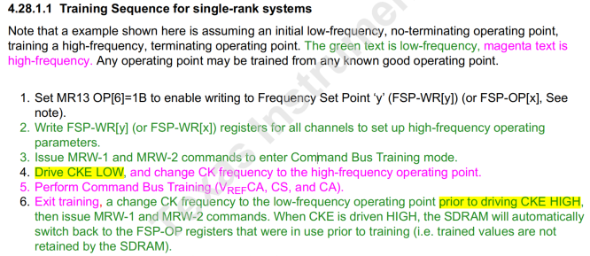
    Figure 1 LPDDR4 Power Ramp and Initialization Sequence
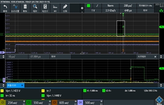
    Figure 2 Actual test waveform of Power Ramp and Initialization Sequence oscilloscope


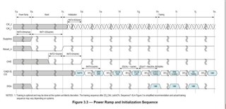
     Figure1 LPDDR4 Power Ramp and Initialization Sequence(from datasheet)

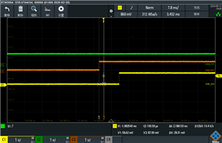
Figure 2 LPDDR4 Power Ramp and Initialization Sequence(we test scope)

  • This is expected as CKE will be driven low during Command Bus Training.  Please see Command Bus Training sequences in the JEDEC spec

    Regards,

    James

  • Hi JJD:

     Thank you your teply,but my quention is why CHE has a 10us pluse ,whitch cause LDDR4 sequence tINT2,tINT3 <2ms,this paramenter does not meet the LDDR4 sepuence requirement.

  • Hi, i guess i'm confused by your comment that it doesn't meet the spec.  TINIT2 is minimum CKE low time before RESET_n high.  This is certainly met in the scope shot, as CKE is low from the beginning of the scope shot beyond when RESET_n goes high.  TINIT3 is min CKE low time after RESET_n high.  The delta you show between markers 1 and 2 is greater than 2ms, so this parameter is also met.

    Can you explain which part of the scope shot doesn't meet spec?

    Regards,

    James

  • Hi JJD:

         Thank you your teply,We have unfolded the waveform above, so the measurement is inaccurate. Please refer to the picture below, tINIT3=1.686ms<2ms, But the LDRR4 manual requires tINIT>2ms.Without this 10us pulse, I believe tINIT3 meets the requirements of the LPDDR4 datsheet and I did not see this pulse through the datasheet LPDDR4 power on timing.I have also consulted with the LPDDR4 manufacturer regarding this issue, and they told me that this signal is controlled by SOC. They advised us to consult with the original TI factory.

  • Can you send the DDR configuration file that you are using (*.dtsi or *.h and *.syscfg)?

    Regards,

    James

  • Hi JJD:

      Plaese see this case , about LPDDR write sequnce ,that is me post to you,and has we ddr config,you can download from there:

      https://e2e.ti.com/support/microcontrollers/arm-based-microcontrollers-group/arm-based-microcontrollers/f/arm-based-microcontrollers-      forum/1431360/am2432-soc-writing-lpddr4-timing-error/5609000#5609000


  • I don't think we have seen this before.  Let me check in our lab on one of our EVMs

    Regards,

    James

  • I went into the lab and our EVM shows the proper 2ms delay

    So i'm not sure why you are seeing less.  Can you send schematic and probe points?  It appears your RESET signal is being pulled high, not driven high.

    Regards,

    James


  • Hi JJD:

     Thank you for you reply,your test waveform, looks like it just meets the 2ms, but have you expanded the waveform to measure the time between RESET and the rising edge of CKE or 2ms? my lpdd4 schematic as shown in the figure below,and  the test point was an overbore dug on this side of LPPD4.

     Figure 1 lpdd4 schematic

    I think my test waveform is the same as yours, except that my time doesn't meet the 2ms(I still tested other boards and found most modules tINIT3 close to 2ms, about 1.96ms), so my CKE is drivened high,not bing pulled high.my claim SOC why this pulse is triggered, because LPDDR4 timing does not have this pulse, currently our test department thinks this time does not meet the LPDDR4 specification, not pass, so can TI side solve the problem, if not, need to explain whether this problem will cause any impact.

  • The pulldown on the RESET signal should be 10K (not 2.2K), and you need to remove the capacitor.  The capacitor is most likely the problem, as this is slowing the rise time of the signal.  This is probably why you are measuring a little less than 2ms.

    I zoomed in and measured on my board, and the time meets the 2ms minimum.  

    The init diagram you posted does not take into consideration the time when CKE is low during Command Bus Training.  Please refer to this portion of the spec:

    After the 2ms TINIT3, the controller will issue training commands and drive CKE low as described for CBT.

    Regards,

    James