This thread has been locked.

If you have a related question, please click the "Ask a related question" button in the top right corner. The newly created question will be automatically linked to this question.

MSPM0G1519: TIMG12 capture using external 32MHz clock and external 1Hz latch signals

Part Number: MSPM0G1519
Other Parts Discussed in Thread: SYSCONFIG, MSPM0G3507, LP-MSPM0G3507

Tool/software:

How do you control the TIMG12 (32-bit timer) to do a period capture using an external ~32MHz clock source and an external 1Hz clock signal?

The Technical Reference Manual (slau846b) states:

27.2.1.1 Clock Source Select and Prescaler
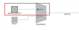
The TIMx clock (TIMCLK) can be sourced from an internal clock or an external signal trigger to advance the clock.

So how is this done? I tried SYSCONFIG many ways but not possible.

I need to count how many external 32MHz clocks occur within the 1 sec external clock signal (rising edge to rising edge).

  • The idea is that you (e.g.) bring the 1kHz signal (capture trigger) into C0, and the 32MHz (clock) signal into C1. Then you set CC1's ACOND=1 (rising edge of C1 pin) and set CTRCTL:CAC=1 to point to CC1's ACOND. After that it's a normal "period" capture on CC0.

    I think example timx_timer_mode_capture_edge_capture will get you the capture part:

    https://dev.ti.com/tirex/explore/node?node=A__ALfbfSw7t-el4gbNzBJSJg__MSPM0-SDK__a3PaaoK__LATEST

    Sysconfig doesn't seem to want to allow setting ACOND to anything but TIMCLK (=0). You may have to explicitly call (I think this is about right):

    > DL_Timer_setCaptureCompareCtl(TIMER, DL_TIMER_CC_MODE_COMPARE, DL_TIMER_CC_ACOND_TRIG_RISE, 1); // ACOND=1 for clock rising on C1

    Along with

    DL_Timer_setCounterControl(TIMER,DL_TIMER_CZC_CCCTL0_ZCOND,DL_TIMER_CAC_CCCTL1_ACOND,DL_TIMER_CLC_CCCTL0_LCOND); // CAC->CC1's ACOND

    The difference between successive captures is the number of (32MHz) cycles.

    [Edit: Forgot the Example link.]

  • Hi, 

    The idea is that you (e.g.) bring the 1kHz signal (capture trigger) into C0, and the 32MHz (clock) signal into C1. Then you set CC1's ACOND=1 (rising edge of C1 pin) and set CTRCTL:CAC=1 to point to CC1's ACOND. After that it's a normal "period" capture on CC0.

    That's a good idea and worthy to try.

    32MHz control the counter advance and 1kHz control the counter clear.

    Hi, 

    he Technical Reference Manual (slau846b) states:

    This part is a timer's clock source description.

    For G3519's TIMG12 clock source, you can choose BUSCLK, MFCLK and LFCLK.

    MFCLK can source from external HFCLK, but have max frequency limitation, and can not reach 32MHz.

    You can config this part in syscfg, clock tree view.

    Regards,

    Helic

  • Thank you guys for your suggestions. I will have to get a demo board or build a quicky board of just the G1519 to test this because it's a major blocking point before settling on this part for my product development.

    Two questions:
    Q1) It's unclear what Helic's comment means. I came across the same 4MHz freq limitation on HFCLK, so I wondered how to select an external 32MHz clock source. However, It sounds like Helic is saying it's not possible, but Bruce is saying it is possible, but not through SYSCONFIG???
    Therefore, I don't understand if you two are in agreement or disagreement. Can you clarify?

    Q2) BTW, it's a 1Hz signal not a 1KHz signal, but not sure that matters with TIMG12 being a 32-bit timer.

    Q3) SUGGESTION: I like the graphical clock tracing in SYSCONFIG for system clocks, so why not add TIMER clocking into that, also?

  • I think [Helic will correct me?] that Helic was describing using the 32MHz signal to provide one of the system clocks, and routing that to the timer as TIMCLK.

    I was describing using the 32MHz as a counter-trigger via the (e.g.) C1 pin.

    Digging a bit further, I think I see the terminology conflict: I think of this (the 32MHz via C1) as a "timer clock" since it drives the counter to tick; the designers consider this a Compare unit feature that (also) causes the counter to tick. Helic (and Sysconfig) are correct that the TIMCLK that runs the rest of the timer unit needs to be one of the system clocks. (This presumably needs to be >=32MHz; BUSCLK seems like a good bet.)

    The model for this is described in TRM (SLAU846B) Sec 27.2.3.2.1 and illustrated in example timx_timer_mode_compare_edge_count:

    https://dev.ti.com/tirex/explore/node?node=A__AAR6edrrZqUYodAtIjBtSQ__MSPM0-SDK__a3PaaoK__LATEST

    In the Example this is done in Driverlib via a (synthesized) mode "DL_TIMER_COMPARE_MODE_EDGE_COUNT" which does the things I described above. I'm not a Sysconfig wizard, but I didn't find a mechanism to Also set the other channel (C0) for Capture. I'm pretty sure the timer unit is capable of it.

  • 你好 Helic, 
    我的中文名字叫史登义,我去过上海三次,多年前在台湾居住过,是个红毛洋鬼子。Grinning

    I cannot find a G3519 Launchpad (none available). If you (or Bruce) have one available, can you please do the experiment that Bruce suggested?
    Connect an external 1Hz signal (capture trigger) into C0, and an external 32MHz (clock) signal into C1 to verify this will work?

    I must verify this before selecting the TI TMSM0G1519 for my application, else I must go to SiLabs part.

    Please help me (请帮我), 

    Dan (史登义) Staver

  • Hi Bruce, 
    Thanks for your latest reply, but there may be some confusion. My external 32MHz clock signal must come from an external IC and NOT one of the internal 32MHz clocks internal to the Gx519.

    You mention BUSCLK, then in section "27.2.1.1.1 Internal Clock and Prescaler", it seems it will be derived from MCLK but that is not the external 32MHz signal I need to advance the clock.

    With all these messages, can we have a quick phone call to clear this up, because it's still not clear if you now believe it will work or not. +1-719-502-1675

    best regards,
    Dan

  • Bruce, 

    The example project you linked to only show the external capture signal but no external clock used.

    Can we have a call or is there any way for someone there with access to any M0G Launchpad that has a 32-bit TIMGx to verify this function?

    best regards,
    Dan

  • What the edge_count Example does is: (1) accepts an input signal into one of the timer Cn pins (2) counts (down) the signal's edges  in the CTR register (3) when the counter reaches 0 (initially 5) it triggers an interrupt for the LOAD event.

    (1)/(2) are the mechanism for accepting your (32MHz) signal into a timer Cn pin, and counting the cycles (rising edges). The next step is to configure the other channel to Capture (the CTR) based on edges in your slower (trigger) signal, arriving on the other channel.

    I don't recommend that you use your 32MHz signal as one of the system clocks. I mentioned ">= 32MHz" since I suspect the timer can't accept a signal faster than the clock (TIMCLK) that it is running on (the datasheet doesn't say) -- LFCLK and MFCLK would be too slow, but I think (without checking) that you can run BUSCLK at least to 40MHz.

  • I never intended to use my external 32MHz as a system clock.

    Are you saying my external 32MHz asynchronous clock has to be qualified by an internal clock before it can advance the TIMG12 as a clock?

    I am planning to buy a MSPM0G3507 Launchpad (3519 Launchpad not available) to prove/disprove this question.

  • Hi, 

    Q1) It's unclear what Helic's comment means. I came across the same 4MHz freq limitation on HFCLK, so I wondered how to select an external 32MHz clock source.

    Yes, it's not possible for the clock system.

    but Bruce is saying it is possible, but not through SYSCONFIG???

    Bruce offer a method to connect external 32MHz to Timer CC pin, this is nor connected to clock system.

    This is some operation in Timer, you need to read the timer register mentioned by Bruce.

    Q2) BTW, it's a 1Hz signal not a 1KHz signal, but not sure that matters with TIMG12 being a 32-bit timer.

    We define TIMG12 as a 32bit timer, only 32bit timer can count the 32MHz to 1s (1Hz) without overflow.

    I think [Helic will correct me?] that Helic was describing using the 32MHz signal to provide one of the system clocks, and routing that to the timer as TIMCLK.
    Q3) SUGGESTION: I like the graphical clock tracing in SYSCONFIG for system clocks, so why not add TIMER clocking into that, also?

    Here is another way:

    We can not bring external 32MHz through clock system to Timer.

    Unless you are using HFCLKIN function, this is a digital clock source for MSPM0, this will bring all MSPM0 system's clock source from external 32MHz.

    Also include the TIMG12. HFCLK_IN_EXT from Device pin to SYSPLL, then to CPU and all peripherals.

    This clock will control the timer count increase.

    Digging a bit further, I think I see the terminology conflict: I think of this (the 32MHz via C1) as a "timer clock" since it drives the counter to tick; the designers consider this a Compare unit feature that (also) causes the counter to tick. Helic (and Sysconfig) are correct that the TIMCLK that runs the rest of the timer unit needs to be one of the system clocks. (This presumably needs to be >=32MHz; BUSCLK seems like a good bet.)

    There will be timer sync issue between external 32MHz to CC input and internal timer clock source, better set timer clock source higher than the input 32MHz.

    There are capture and sync steps for timer to capture the external signal, you can refer to Figure 27-13. Consecutive Period and Majority Voting for Input Glitch Filtering using FP = 0 (3 TIMCLK cycles).

    Sorry, I didn't finish reading all your reply. Time is limited today, too busy. I hope this will guide you well.

    If there is any further question, please reply to this thread,

    Regards,

    Helic

  • I hacked up a program (frequency-counter) I wrote some time ago to do what I described above. With TIMCLK=BUSCLK=32MHz, I was able to count/capture a 16MHz input signal, but not a 32MHz input signal. This suggests (as Helic says) you need TIMCLK > 32MHz (not ">="), though I don't know yet how much ">". My program doesn't currently speed up BUSCLK, so I need to add that.

  • Thank you to both of you for your assistance. I think this boils down to the documentation not being clear.

    From the discussions (and too many years experience with MCUs), I think you are saying that I should be able to use one of the external Cn inputs for advancing the count and the other Cn input for latching (capture) event, but these signals MUST be qualified (synchronized) by the internal TIMCLK which must be derived from a short list of system clocks and must be > the external clock being used. (probably >  1.25x or so to be safe).

    The only real choice to drive TIMCLK is BUSCLK ← MCLK because all other choices are too slow.

    The only way for me to verify is on a Launchpad so I ordered the LP-MSPM0G3507 (only one available) since it also is in the family and has a 32-bit TIMG12.

    I'll let you know what I find, but I'm hoping this will allow choosing this part for my prod development.

  • Hi, 

    There is another way that I mention:

    The only real choice to drive TIMCLK is BUSCLK ← MCLK because all other choices are too slow.
    We can not bring external 32MHz through clock system to Timer.
    HFCLK_IN_EXT from Device pin to SYSPLL, then to CPU and all peripherals.

    But this need external 32MHz continuously input to MSPM0.

    The only real choice to drive TIMCLK is BUSCLK ← MCLK because all other choices are too slow.

    Yes, TIMG12 max clock speed is 80MHz from MCLK.

    Regards,

    Helic

  • Hi, 

    I am back today~

    我的中文名字叫史登义,我去过上海三次,多年前在台湾居住过,是个红毛洋鬼子。

    Glad to hear that~ Nice to meet you. You have so much experience!

    I cannot find a G3519 Launchpad (none available).

    This is internal only now and there are limitation, if you need get one, please contact your local field team.

    And G3507 is also the same for TIMG12, you can use LP-MSPM0G3507 to test this first.

    You mention BUSCLK, then in section "27.2.1.1.1 Internal Clock and Prescaler", it seems it will be derived from MCLK but that is not the external 32MHz signal I need to advance the clock.

    Yes.

    I never intended to use my external 32MHz as a system clock.

    So, we can not bring external 32MHz into MSPM0 as system clock.

    Are you saying my external 32MHz asynchronous clock has to be qualified by an internal clock before it can advance the TIMG12 as a clock?

    Yes, there are some timer cc input sync steps. You can refer to Figure 27-13 in latest version of TRM.

    Regards,

    Helic

  • I've demonstrated the method on a 32MHz input signal using TIMCLK=BUSCLK=64MHz. It's possible it would run with a slower BUSCLK, but I haven't tried it.

  • That's great to hear this!

  • Hi Bruce,

    Thank you very much for verifying this. Last week, I ordered the similar-family Launchpad (LP-MSPM0G3507) but it won't arrive until the end of this week. I'll try it out, as well, but I feel better that you were able to get that working.
    After you explained an internal clock must be used to qualify the external clock, my guess is anything > ~1.25 or 40MHz would suffice. 
    Now that I have the option, if it is fast enough for my application, I may be able to use the internal SYSOSC (32MHz), reduce my external clock to 16MHz, and minimize cost. I have a GPS that will help me keep track of long-term time drift, so I think I should be OK.

    Thanks again for both of you guys' assistance.

    best regards,
    Dan

  • I (still) don't know how to do this with Sysconfig/Driverlib. I've mentioned two possibilities above, but I haven't tried either of them.

    I defer to the Sysconfig wizards.

  • It couldn't be done by syscfg.

    Syscfg can not cover such a non-normal application.

    Of course we can try to use driverlib, just by searching these register in dl_timer.x file.

  • I tried the method using TIMCLK=BUSCLK=48MHz, and I (consistently) see a count of 16M. I suppose that means that BUSCLK needs to be faster than this, probably 64MHz.

  • At least twice the clock speed.

    Tips from TRM: 27.2.3.1.2.3 Pulse Width Capture, Figure 27-16. Pulse-Width Capture Mode

  • I am able to capture using rising edge of TIMG12_C0 but it always uses internal BUSCLK for counting.

    But, after trying everything you all suggested, examined all the example projects' code, as well as played with many register settings, still cannot get the Timer counter to advance using an external clock on pin TIMG12_C1.

    What am I missing?

    Code:

    void CAPTURE_0_INST_IRQHandler(void)
    {
        uint32_t joe = DL_TimerG_getPendingInterrupt(CAPTURE_0_INST) & 0xFF;

    //  switch (DL_TimerG_getPendingInterrupt(CAPTURE_0_INST)) {
        switch (joe) {
            case DL_TIMER_IIDX_CC0_UP: 

                gThisCaptureCnt = DL_TimerG_getCaptureCompareValue(CAPTURE_0_INST, DL_TIMER_CC_0_INDEX);
               
                // if(gNumPpsCaptures > 0) {
                    gPPS_Period = gThisCaptureCnt - gLastCaptureCnt;
                    gCheckCaptures = true;
                // }
                    gLastCaptureCnt = gThisCaptureCnt;
                    gSynced = true;

                    // workaround for errata TIMER_ERR_01 will not work fast enough for 16MHz PPL_clk, may miss clocks
                    // /* Manual reload is needed to workaround timer capture limitation */
                    // DL_TimerG_setTimerCount(CAPTURE_0_INST, gLoadValue);
    ...

    Conditions: (in debug, I get period = gPPS_Period ~ 16155400 ( shows it is using 32MHz BUSCLK and NOT external TIMG12_C1 clock of 4MHz).

    1) 32MHz BUSCLK =SYSCLK
    2) TIMG12_C1 (PINCM6   / PB31 / TIMG12_C1[5] / pin-39) = 4 MHz external clock
    3) TIMG12_C0 (PINCM30 / PB13 / TIMG12_C0[4] / pin-1)   = 2 Hz external clock

    TIMG12_C0 & TIMG12_C1 configuration:
     

    TIMG12 Register values during debug:

  • CAC is pointing to CCCTL_01[1].ACOND, but CCCTL_01[1].ACOND=0 (TIMCLK). You want .ACOND=1 (Rising). 

    I had this idea that you could do this with 

    > DL_Timer_setCaptureCompareCtl(TIMER, DL_TIMER_CC_MODE_COMPARE, DL_TIMER_CC_ACOND_TRIG_RISE, 1); // ACOND=1 for clock rising on C1

    but maybe there's something wrong with this call? [When I did this, I just stored ACOND directly.]

  • Hi Bruce,

    Thanks for your patience. I realized I was completely misunderstanding how the Timer worked, so I tried to forget all previous assumptions, reread the timer description chapters, and now I got it working. This peripheral must have modes I haven't used so they pass the pointer to the CAC->ACOND.

    However, the wording for the IFCTL_01[0/1] had me confused. Eventually, the only settings that work are:

    TIMG12.IFCTL_01[0] = [0, 2] (which both would select C_) pin for the capture event edge)
    TIMG12.IFCTL_01[1] = [0]

    which now makes sense, but eluded my Winnie the Pooh brain for a while.

    I still think it is not well written and it was confusing that they use non-stationary mnemonics for the CCP (Capture Control Pins) which threw me off. It wasn't clear whether they were talking about a pin or a event or what.

    At first, it was also not clear that one has to use both timer registers to accomplish this task. Is that by design or due to the TIMER errata?

    best regards,
    Dan

  • For IFCTL_01[0], ISEL=0 and ISEL=2 are equivalent (since it's channel 0). One usage for ISEL=2 is to set it in IFCTL_01[1], so both channels use the CC0 pin, then set opposite edge-senses so one channel captures rising edges and the other falling edges. This allows you to distinguish which edge triggered, since it's otherwise difficult to figure out.

    Your application did need two channels, since the pins had different signals which drove separate results. In some timer architectures, your high-frequency signal would be fed in as a "clock" -- a special input -- but in this architecture it's just another channel.