This thread has been locked.

If you have a related question, please click the "Ask a related question" button in the top right corner. The newly created question will be automatically linked to this question.

LP-MSPM0G3507: Register level

Part Number: LP-MSPM0G3507
Other Parts Discussed in Thread: MSPM0G3507, SYSCONFIG

Tool/software:

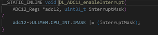
Hello TI, looking to see you you have code book in the register level for the MSPM0G3507 thus far I have done GPIO, UART and interrupts but getting references for it is hard currently working on ADC and I feel like im missing something

  • Hi Ruben!

    Thanks for reaching out!

    What issues are you currently experiencing with the ADC?

    -Matthew

  • not getting data, not sure if i have the setup correctly

    #include "ti/devices/msp/m0p/mspm0g350x.h"
    #include "ti/driverlib/dl_adc12.h"
    #include "ti/driverlib/dl_common.h" // For DL_Common_delayCycles function
    #include "ti_msp_dl_config.h"
    #include "IndexMacros.h"
    #include "stdio.h"
    uint16_t threshold = 1;//16384 / 2; // VCC/2 or 1.15V
    int i=0;
    //data = (V * 4095) / 3.3V
    int main (void)
    {
      //IOMUX->SECCFG.PINCM[58] = Ox00040081;
    
      ADC0->ULLMEM.GPRCM.RSTCTL = 0xB1000003; // reset
      ADC0->ULLMEM.GPRCM.PWREN = 0x26000001;  // activate
      DL_Common_delayCycles(24);              // wait
    
      ADC0->ULLMEM.GPRCM.CLKCFG = 0xA9000000; // ULPCLK
      ADC0->ULLMEM.CLKFREQ = 7;               // 40-48 MHz
      ADC0->ULLMEM.CTL0 = 0x03010000;         // divide by 8
      ADC0->ULLMEM.CTL1 = 0x00000000;         // mode
      ADC0->ULLMEM.CTL2 = 0x00000000;         // MEMRES
      ADC0->ULLMEM.MEMCTL[0] = 1;             // channel 1 is PA26
      ADC0->ULLMEM.SCOMP0 = 0;                // 8 sample clocks
      //ADC0->ULLMEM.CPU_INT.IMASK = 0;         // no interrupt
    
       ADC0->ULLMEM.CTL0 |= 0x00000001;             //  enable conversions
       ADC0->ULLMEM.CTL1 |= 0x00000100;             //  start ADC
       uint32_t volatile delay=ADC0->ULLMEM.STATUS; //  time to let ADC start
    
    NVIC->IP[1] = 1<<4; // ADC0 is IRQ 4
    NVIC->ISER[0] = 1<<4; 
    NVIC->IP [1] = (NVIC->IP [1] & (~0xFF000000)) | (2<<6) ;  
    __enable_irq();
    
      while(1)
      {
      // printf("waiting\n");
      __WFI();
      }
             
    }
    void ADC0_IRQHandler(void)
    {
        uint16_t adcRaw = ADC0->ULLMEM.MEMRES[0];
    
        if (adcRaw > threshold) // Vcc/2 -> 3.04/2
        {
          i=i+1;
          printf("%d \n", i);
        }
    
    }
    
  • If anyone can help please, any input will be amazing

  • you still active?

  • I haven't decoded these bits yet (they do all have CMSIS names), but to narrow things down:

    How do you tell that you're not getting data? (Breakpoint in ISR? MEMRES==0? Fault?) What is connected to the ADC input?

  • i have a simple infrared sensor that triggers if my finger passes thru it

  • How do you know you're not getting data?

  • Hi Ruben,

    I will commend you to configure ADC by importing SDK example and configuring by sysconfig, which is a graphic tool for code generation. And if you want to build a register level project, you could just follow the generated code, and copy the register level code into your project.

    As for the ADC code attached, have you enabled the ADC interrupt? such as

  • never tried it in that way since in the msp432 we didn't do that either 

  • It is necessary to enable interrupt for MSPM0. Please see the ADC initial process for MSPM0 example adc12_sequence_conversion

        DL_ADC12_setClockConfig(ADC12_0_INST, (DL_ADC12_ClockConfig *) &gADC12_0ClockConfig);
    
        DL_ADC12_initSeqSample(ADC12_0_INST,
            DL_ADC12_REPEAT_MODE_DISABLED, DL_ADC12_SAMPLING_SOURCE_AUTO, DL_ADC12_TRIG_SRC_SOFTWARE,
            DL_ADC12_SEQ_START_ADDR_00, DL_ADC12_SEQ_END_ADDR_03, DL_ADC12_SAMP_CONV_RES_12_BIT,
            DL_ADC12_SAMP_CONV_DATA_FORMAT_UNSIGNED);
        DL_ADC12_configConversionMem(ADC12_0_INST, ADC12_0_ADCMEM_0,
            DL_ADC12_INPUT_CHAN_2, DL_ADC12_REFERENCE_VOLTAGE_VDDA, DL_ADC12_SAMPLE_TIMER_SOURCE_SCOMP0, DL_ADC12_AVERAGING_MODE_DISABLED,
            DL_ADC12_BURN_OUT_SOURCE_DISABLED, DL_ADC12_TRIGGER_MODE_AUTO_NEXT, DL_ADC12_WINDOWS_COMP_MODE_DISABLED);
        DL_ADC12_configConversionMem(ADC12_0_INST, ADC12_0_ADCMEM_1,
            DL_ADC12_INPUT_CHAN_0, DL_ADC12_REFERENCE_VOLTAGE_VDDA, DL_ADC12_SAMPLE_TIMER_SOURCE_SCOMP0, DL_ADC12_AVERAGING_MODE_DISABLED,
            DL_ADC12_BURN_OUT_SOURCE_DISABLED, DL_ADC12_TRIGGER_MODE_AUTO_NEXT, DL_ADC12_WINDOWS_COMP_MODE_DISABLED);
        DL_ADC12_configConversionMem(ADC12_0_INST, ADC12_0_ADCMEM_2,
            DL_ADC12_INPUT_CHAN_7, DL_ADC12_REFERENCE_VOLTAGE_VDDA, DL_ADC12_SAMPLE_TIMER_SOURCE_SCOMP0, DL_ADC12_AVERAGING_MODE_DISABLED,
            DL_ADC12_BURN_OUT_SOURCE_DISABLED, DL_ADC12_TRIGGER_MODE_AUTO_NEXT, DL_ADC12_WINDOWS_COMP_MODE_DISABLED);
        DL_ADC12_configConversionMem(ADC12_0_INST, ADC12_0_ADCMEM_3,
            DL_ADC12_INPUT_CHAN_3, DL_ADC12_REFERENCE_VOLTAGE_VDDA, DL_ADC12_SAMPLE_TIMER_SOURCE_SCOMP0, DL_ADC12_AVERAGING_MODE_DISABLED,
            DL_ADC12_BURN_OUT_SOURCE_DISABLED, DL_ADC12_TRIGGER_MODE_AUTO_NEXT, DL_ADC12_WINDOWS_COMP_MODE_DISABLED);
        DL_ADC12_setPowerDownMode(ADC12_0_INST,DL_ADC12_POWER_DOWN_MODE_MANUAL);
        DL_ADC12_setSampleTime0(ADC12_0_INST,160);
        /* Enable ADC12 interrupt */
        DL_ADC12_clearInterruptStatus(ADC12_0_INST,(DL_ADC12_INTERRUPT_MEM3_RESULT_LOADED));
        DL_ADC12_enableInterrupt(ADC12_0_INST,(DL_ADC12_INTERRUPT_MEM3_RESULT_LOADED));
        DL_ADC12_enableConversions(ADC12_0_INST);

    In this case, ADC result load interrupt is enabled, so that ADC interrupt handler could be entered when ADC result is loaded.