This thread has been locked.

If you have a related question, please click the "Ask a related question" button in the top right corner. The newly created question will be automatically linked to this question.

TPS51386: Problem in the Schematic design

Part Number: TPS51386

Tool/software:

Hi Support,

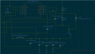
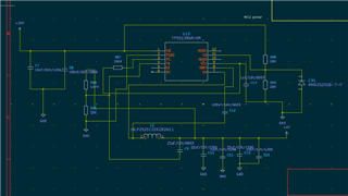
Currently I have Design the Schematic 

Input Voltage is 24V

Output Voltage is 5V

but i have get it 0.8V only at output point.


regards

Saurav

  • Hi Saurav,

    The VCC capacitor value is wrong (C14). It should be1uF, not 1nF. Pls change it. When you power on the device, pls test VCC and EN voltage at first. If these two voltages are wrong, the device cannot work normally. Thanks.

    Aurora

  • I have placed the 1uf  till not getting voltage on the pins.

  • Hi Saurav,

    If you cannot get VCC voltage after start up, this may be caused by the chip being damaged or not being soldered properly. If the chip is well soldered, you should be able to detect a diode to ground between each pin and GND using a multimeter. Please eliminate these problems first. In addition, the power supply can be current limited when powered on for the first time, and the initial debugging voltage can be lower, such as 12V. Please make sure that the chip has EN and VCC voltages after power-on, and the voltage values ​​are normal (from your schematic, they should all be 5V). Thanks.

    Aurora