This thread has been locked.

If you have a related question, please click the "Ask a related question" button in the top right corner. The newly created question will be automatically linked to this question.

MSPM0C1104: specific pwm output pins are not output.

Part Number: MSPM0C1104
Other Parts Discussed in Thread: SYSCONFIG,

Tool/software:

Hi Experts,

My customer is developing the LED Lamp with MSPM0C1104SDYYR(16pin)

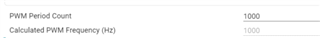
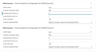
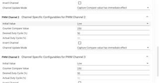
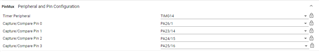
they need 7 PWM outputs, so they set it as follows. however, PA24 and PA25 of TIMG14 are not output.

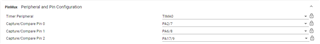
I attached the sysconfig file.

could you check if there is anything we missed in the setup?

empty_mspm0c1104.zip

thanks

Regards

  • Hello Robin,

    Firstly, check whether you "start the timer" in your code because I found that you didn't start timer in your Sysconfig. 

    Secondly, check whether you set the duty cycle in your code because I found that the duty cycle in your Sysconfig is 0. You use the Center-aligned, in this mode, set 500 will let your duty cycle become 0. About the different aligned method, please refer to the technical reference manual which can be downloaded from ti.com.

    And because the initial value is low, at the same time, the duty cycle is 0, so the output will always be zero. I think you know that the duty cycle stands for the proportion of high level (logic1) width throughout the entire cycle. 

    I have tried on my side using below configuration, PA24 and PA25 can output PWM normally.

    More details about PWM generation, please learn about the TRM. 

    Best Regards,

    Janz Bai

  • Hi Janz,

    Thanks for reply.

    they set the Duty and start PWM output with the sw as below.

    long Sys_AllPwmDuty(uint16_t Duty)
    {
    #if defined(DEV_PWM)
    uint32_t duty_cycle_count;

    duty_cycle_count = 1000 - (1000*Duty)/100;
    DL_TimerG_setCaptureCompareValue(PWM_0_INST, duty_cycle_count, DL_TIMER_CC_0_INDEX);
    DL_TimerG_setCaptureCompareValue(PWM_0_INST, duty_cycle_count, DL_TIMER_CC_1_INDEX);
    DL_TimerG_setCaptureCompareValue(PWM_0_INST, duty_cycle_count, DL_TIMER_CC_2_INDEX);
    DL_TimerG_setCaptureCompareValue(PWM_0_INST, duty_cycle_count, DL_TIMER_CC_3_INDEX);
    DL_TimerA_setCaptureCompareValue(PWM_1_INST, duty_cycle_count, DL_TIMER_CC_0_INDEX);
    DL_TimerA_setCaptureCompareValue(PWM_1_INST, duty_cycle_count, DL_TIMER_CC_1_INDEX);
    DL_TimerA_setCaptureCompareValue(PWM_1_INST, duty_cycle_count, DL_TIMER_CC_2_INDEX);
    #else
    uint32_t duty_cycle_count;

    duty_cycle_count = 1000 - (1000*Duty)/100;
    DL_TimerG_setCaptureCompareValue(PWM_0_INST, duty_cycle_count, DL_TIMER_CC_0_INDEX);
    #endif
    return E_OK;
    }

    /*******************************************************************************
    * Function Name : Sys_PwmStart
    * Description : Start PWM Timer
    * Input : None
    * Output : None
    * Return : ERROR/OK
    *******************************************************************************/
    long Sys_PwmStart(void)
    {
    #if defined(DEV_PWM)
    DL_TimerG_startCounter(PWM_0_INST);
    DL_TimerA_startCounter(PWM_1_INST);
    #else
    DL_TimerG_startCounter(PWM_0_INST);
    #endif
    return E_OK;
    }

    Another PWM channels output normally, but only PA24 and PA25 pins do not work.

    We will follow your guide and ask you a question again.

    thanks

    B.R

  • Hello Robin,

    I am out of office today and I will reply to you soon,

  • Hello Robin,

    I think you can try to do some tests step by step:
    Mimimum your code, only keep the TIMERG14 and PA24 PA25 output a PWM with fixed duty cycle. If it can't work, maybe the PA24 PA25 on your MCU is damaged by kinds of reason, you need to change another chip. If it can work, you can add other function step by step to check whether there is some issue of your code logic.

    Best Regards,

    Janz Bai