This thread has been locked.

If you have a related question, please click the "Ask a related question" button in the top right corner. The newly created question will be automatically linked to this question.

AM2732: Synchronisation of ePWMA and ePWMB

Genius 3215 points

Part Number: AM2732

Tool/software:

Hi Al,

My customer want to synchronise ePWMA and ePWMB by performing SYNC OUT when ePWMA's TBCTR reaches 0 and ePWMB's count is set to 0 (same as ePWMA).

Use the following sample code
mcu_plus_sdk_am273x_09_02_00_52\examples\drivers\epwm\epwm_duty_cycle

SYNCOUT setting for ePWMA and PHSEN setting for ePWMB.
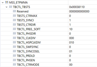
The ePWMA registers are as follows.
SYNCOSEL=0x01 and SYNC OUT is implemented when TBCTR is set to 0.
[Question]

For example, when I change the TBPHS of the ePWM to “1”, I feel that the TBCTR of the ePWMB is not set to “1” when the TBCTR of the ePWMA is set to 0. (as the output waveform does not change)
I would like to confirm that this setting is correct.
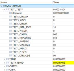
PHSEN is set to 1, but I feel that the SYNC OUT of the ePWMA is not recognised (I am concerned that the SYNCI bit is also 0).
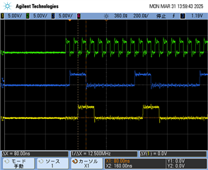
There is no problem with the output waveform.
Check that the ePWMA and ePWMB continue to synchronise with this setting.
Best Regards,

Ito

  • Hi Ito,

    Thanks for reaching out to e2e.

    Can you clarify if there is a waveform issue for the usecase? These two comments conflict, so I am unsure if the problem is in waveforms or only in the CCS.

    -

    as the output waveform does not chang

    -

    There is no problem with the output waveform

    Secondly, it sounds like you are asking if the register settings and values from the screenshots are correct for TBCTR and TBPHS in mcu_plus_sdk_am273x_09_02_00_52\examples\drivers\epwm\epwm_duty_cycle. Is this correct?

    Best,

    Haley

  • Hi Alexander,

    Thank you for your reply.

    There is no problem with the attached waveform, but they are not sure if it will stay synchronised all the time.
    What the customer wants to check is the correct register settings to synchronise ePWMA and ePWMB.

    If “1” is put in TBPHS, the TBCTR of ePWMB should be set to “1” when the TBCTR of ePWMA is set to “0”.
    However, the customer believes that the current setting is incorrect because the output waveform does not change.

    -In other words, they dared to change the settings to check if the settings are correct and tried to change the waveform, but failed.

    [Question]

    Please check if the register settings in the first attached image can be synchronised without problems.

    Secondly, it sounds like you are asking if the register settings and values from the screenshots are correct for TBCTR and TBPHS in mcu_plus_sdk_am273x_09_02_00_52\examples\drivers\epwm\epwm_duty_cycle. Is this correct?

    yes.

    Best Regards,

    Ito

  • Hi Ito,

    Thanks very much clarifying. This will take a bit of time. I will post an update on 4 April.

    Best,

    Haley

  • Hi Ito,

    The ePWMB TBCTL_PHSEN value looks correct, but can you confirm if the values from the ePWMB screenshot are from before or after running epwm_duty_cycle example? And was epwm_duty_cycle example modified in anyway?

    I am asking because the code calls "EPWM_tbSyncDisable()" which will disable the synchronization. (Even if sync-in event occurs the count value will not be reloaded. Link at the end of post.)

    If ePWMB ran epwm_duty_cycle without any edits, this may explain the issue, but I still need time to check the other ePWMB items. I can give another update on 9 April.

    Thanks,

    Haley

    https://dev.ti.com/tirex/content/mcu_plus_sdk_am273x_09_02_00_52/docs/api_guide_am273x/group__DRV__EPWM__MODULE.html#ga49bd10727c0dc4329e8bee9dd362f00b

  • Hi Haley,

    Thank you for your reply.

    The ePWMB TBCTL_PHSEN value looks correct, but can you confirm if the values from the ePWMB screenshot are from before or after running epwm_duty_cycle example? And was epwm_duty_cycle example modified in anyway?

    ePWMB is the value after  running epwm_duty_cycle example.

    Please see the code below for the modifications.

    #include <kernel/dpl/DebugP.h>
    #include <kernel/dpl/AddrTranslateP.h>
    #include <kernel/dpl/SemaphoreP.h>
    #include <kernel/dpl/HwiP.h>
    #include <kernel/dpl/ClockP.h>
    #include <drivers/epwm.h>
    #include "ti_drivers_config.h"
    #include "ti_drivers_open_close.h"
    #include "ti_board_open_close.h"
    
    //Stop the clock with MSS_EPWMCONFG, 
    //ePWM settings and add #define to make it work.
    #define ADDR_MSS_EPWMCONFIG             (*(volatile uint32_t*)(0x02120090))
    
    /* Global variables and objects */
    static HwiP_Object       gEpwmHwiObject_Pwm0;
    static HwiP_Object       gEpwmHwiObject_Pwm1;
    static SemaphoreP_Object gEpwmSyncSemObject;
    
    /* Function Prototypes */
    static void App_epwmIntrISR_Pwm0(void *handle);
    static void App_epwmIntrISR_Pwm1(void *handle);
    static void App_epwmConfig(void);
    
    /* variable to hold base address of EPWM that is used */
    uint32_t gGpioBaseAddr;
    
    uint32_t gEpwmBaseAddr_Pwm0;
    uint32_t gEpwmBaseAddr_Pwm1;
    uint32_t gEpwmBaseAddr_Pwm2;
    
    
    void epwm_duty_cycle_main(void *args)
    {
        int32_t             status;
        HwiP_Params         hwiPrmsPwm0, hwiPrmsPwm1;
    
        /* Open drivers to open the UART driver for console */
        Drivers_open();
        Board_driversOpen();
    
        DebugP_log("EPWM Duty Cycle Test Started ...\r\n");
        DebugP_log("Please refer EXAMPLES_DRIVERS_EPWM_DUTY_CYCLE example user \
    guide for the test setup to probe EPWM signal. \r\n");
        DebugP_log("App will wait for 60 seconds (using PWM period ISR) ...\r\n");
    
        /* Get address after translation translate */
        gGpioBaseAddr = (uint32_t) AddrTranslateP_getLocalAddr(GPIO_LED_BASE_ADDR);
        GPIO_setDirMode(gGpioBaseAddr, GPIO_LED_PIN, GPIO_LED_DIR);
    
        /* Address translate */
        gEpwmBaseAddr_Pwm0 = (uint32_t)AddrTranslateP_getLocalAddr(CONFIG_EPWM0_BASE_ADDR);
        gEpwmBaseAddr_Pwm1 = (uint32_t)AddrTranslateP_getLocalAddr(CONFIG_EPWM1_BASE_ADDR);
        gEpwmBaseAddr_Pwm2 = (uint32_t)AddrTranslateP_getLocalAddr(CONFIG_EPWM2_BASE_ADDR);
    
        /* Stop all three channels with epwmconfig in MSS_CTRL */
        ADDR_MSS_EPWMCONFIG = 0x00000000;
    
        /* Configure PWM */
        App_epwmConfig();
    
        /* START */
        ADDR_MSS_EPWMCONFIG = 0x07000000;
    
        while(1)
        {
            ;
        }
    
        EPWM_etIntrDisable(gEpwmBaseAddr_Pwm0);
        EPWM_etIntrClear(gEpwmBaseAddr_Pwm0);
        EPWM_etIntrDisable(gEpwmBaseAddr_Pwm1);
        EPWM_etIntrClear(gEpwmBaseAddr_Pwm1);
        HwiP_destruct(&gEpwmHwiObject_Pwm0);
        HwiP_destruct(&gEpwmHwiObject_Pwm1);
        SemaphoreP_destruct(&gEpwmSyncSemObject);
    
        DebugP_log("EPWM Duty Cycle Test Passed!!\r\n");
        DebugP_log("All tests have passed!!\r\n");
    
        Board_driversClose();
        Drivers_close();
    }
    
    static void App_epwmConfig(void)
    {
        /* ePWMA=triggerA */
        /* TBSTS phsen=0 */
        *(volatile uint32_t *)gEpwmBaseAddr_Pwm0      = 0x00018110;
        /* TBPRD */
        *(volatile uint32_t *)(gEpwmBaseAddr_Pwm0+8)  = 0x001F0000;
        /* CMPA */
        *(volatile uint32_t *)(gEpwmBaseAddr_Pwm0+16) = 0x00070000;
        /* AQCTLA + CMPB */
        *(volatile uint32_t *)(gEpwmBaseAddr_Pwm0+20) = 0x0121000F;
        
        /* ePWMB=triggerB */
        *(volatile uint32_t *)gEpwmBaseAddr_Pwm1      = 0x00018104;
        /* TBPRD */
        *(volatile uint32_t *)(gEpwmBaseAddr_Pwm1+8)  = 0x001F0000;
        /* CMPA */
        *(volatile uint32_t *)(gEpwmBaseAddr_Pwm1+16) = 0x00030000;
        /* AQCTLA + CMPB */
        *(volatile uint32_t *)(gEpwmBaseAddr_Pwm1+20) = 0x0121000B;
    
        /* ePWMC=12.5MHz output */
        *(volatile uint32_t *)gEpwmBaseAddr_Pwm2      = 0x00018000;
        /* TBPRD */
        *(volatile uint32_t *)(gEpwmBaseAddr_Pwm2+8)  = 0x000f0000;
        /* CMPA */
        *(volatile uint32_t *)(gEpwmBaseAddr_Pwm2+16) = 0x00070000;
        /* AQCTLA + CMPB */
        *(volatile uint32_t *)(gEpwmBaseAddr_Pwm2+20) = 0x02240007;
    }

    Best Regards,

    Ito

  • Hi Ito,

    I finished reviewing the registers and code. Even though the registers values are correct for the usecase, I have four suggestions for code modifications which may help with the issue.

    These suggestions are based on epwm_duty_cycle, a similar use case in Controlling Multiple Buck Converters With Same Frequencies section from the TRM, and EPWM APIs (link to APIs at the end).

    • Set AQCTLA CAD and CBD bits to b'1 for CLEAR (also known as EPWM_AW_ACTION_LOW)
      • This is the main difference to check
    • Use EPWM_tbSyncEnable to ensure the TBPHS register is set with a value
      • Screenshots and code didn't show TBPHS registers for both epwms
    • Use more of the APIs and epwm_duty_cycle code
      • Example: Using EPWM_tbSetSyncOutMode(gEpwmBaseAddr_Pwm1, EPWM_TB_SYNC_OUT_EVT_SYNCIN); and EPWM_tbSetSyncOutMode(gEpwmBaseAddr_Pwm0, EPWM_TB_SYNC_OUT_EVT_CNT_EQ_ZERO);
    • One can also try modifying the usecase requirements to either utilize SWFSYNC bit to force synchronization pulse

    Link: https://dev.ti.com/tirex/content/mcu_plus_sdk_am273x_09_02_00_52/docs/api_guide_am273x/group__DRV__EPWM__MODULE.html#gaa19cd037728952934ce0e5b08ab55c4d

    Thanks,

    Haley

  • Hi Haley,

    Thank you for your reply.

    I will check the information you have given me.

    [Question]
    Is the phenomenon correct that the TBCTR of ePWMB becomes “1” when the TBCTR of ePWMA is set to 0, even if TBPHS is changed to “1”?

    Best Regards,

    Ito

  • Hi Ito,

    If the TBPHS you are referring to is for ePWMB, then yes.

    This is because:

    • ePWMA is supposed to send the SYNC OUT signal  when the TBCTR is 0 for your usecase (quote below). Then, this SYNC OUT goes into ePWMB's EPWMxSYNCI
      • SYNC OUT when ePWMA's TBCTR reaches 0
    • Time-Base Counter Synchronization TRM's section description of "EPWMxSYNCI: Synchronization Input Pulse"
      • The value of the phase register is loaded into the counter register when an input synchronization pulse is
        detected (TBPHS → TBCTR). This operation occurs on the next valid time-base clock (TBCLK) edge.

    Overall, TBCTR becomes a "1" because TBPHS is a "1". Please note that I am assuming a valid clock edge and ignoring the screenshot of EPWMB_SYNCI = 0 in this answer. Let me know if I need to consider all previous posts or parts of previous posts for any future questions.

    Thanks,

    Haley