


Other Parts Discussed in Thread: HALCOGEN
Tool/software:
I’m working with two LaunchPad development boards using the TMS570LS1224 microcontroller. One board is configured as the SPI master, and the other as the SPI slave.
I need to use SPI receive interrupts on both master and slave sides when a data byte is received via SPI. Both boards are connected using SPI3.
On the master board, the interrupt works correctly when I use the function:
spiEnableLoopback(spiREG3, Digital_Lbk);
In this case, the interrupt triggers properly, and the LED connected to PORTB GIO pin 2 turns on as expected.
However, when I apply the necessary configuration for the slave to work with receive interrupts (instead of loopback), the interrupt does not trigger on the slave when the master sends data.
Note: I have ruled out wiring issues, since the slave does receive the data correctly using polling mode. The issue seems to be specific to using interrupts on the slave side.
Can you please help me figure out why the SPI RX interrupt doesn't work on the slave when connected to the master, even though it works in loopback mode?
I’ve attached the CCS code and HALCoGen settings for the master and slave below.
Master Code CSS
/* USER CODE BEGIN (0) */
#include "sci.h"
#include "gio.h"
#include "string.h"
#include "stdio.h"
#include "stdlib.h"
#include "spi.h"
/* USER CODE END */
/* Include Files */
#include "sys_common.h"
/* USER CODE BEGIN (1) */
// Global Variables
uint16 Tx_SPI[1] = { 0x00 }; // SPI transmit buffer
uint16 Rx_SPI[1] = { 0x00 }; // SPI receive buffer
spiDAT1_t dataconfig1_t;
unsigned char Command_String[4] = { 0 }; // Buffer to store command string from SCI
// Variable to hold received command from SCI
unsigned char command;
// Variables for command processing
uint16_t index = 0; // Index for command string buffer
uint16_t flag = 0; // Flag indicating data is ready to be sent via SPI
/* USER CODE END */
/** @fn void main(void)
* @brief Application main function
* @note This function is empty by default.
*
* This function is called after startup.
* The user can use this function to implement the application.
*/
/* USER CODE BEGIN (2) */
/* USER CODE END */
int main(void)
{
/* USER CODE BEGIN (3) */
gioInit();
sciInit();
spiInit();
_enable_IRQ();
// SPI configuration: using SPI3 and chip select = 1
dataconfig1_t.CS_HOLD = TRUE;
dataconfig1_t.WDEL = TRUE;
dataconfig1_t.DFSEL = SPI_FMT_0;
dataconfig1_t.CSNR = SPI_CS_1;
gioSetBit(gioPORTB, 1, 0);
spiREG3->INT0 |= (1U << 8); // Enable SPI receive interrupt
spiEnableNotification(spiREG3, spiREG3->INT0); // Enable SPI RX interrupt notification
sciReceive(scilinREG, 1, (unsigned char*) &command);
spiGetData(spiREG3, &dataconfig1_t, 1, Rx_SPI);
// Test loop with loopback mode
//spiEnableLoopback(spiREG3, Digital_Lbk);
while (1)
{
if(flag == 1){
//spiTransmitAndReceiveData(spiREG3, &dataconfig1_t, 1, Tx_SPI, Rx_SPI);
//spiTransmitData(spiREG3, &dataconfig1_t, 1, Tx_SPI);
spiSendData(spiREG3, &dataconfig1_t, 1, Tx_SPI);
flag = 0;
}
}
/* USER CODE END */
return 0;
}
/* USER CODE BEGIN (4) */
void sciNotification(sciBASE_t *sci, uint32 flags)
{
uint16_t Buffer;
sciReceive(scilinREG, 1, (unsigned char*) &command);
if (command != '?')
{
Command_String[index] = command;
++index;
}
else
{
// When '?' is received, convert the command string to a number
Buffer = (uint16_t) atoi((const char*) Command_String);
Tx_SPI[0] = Buffer; // Assign the converted value to the SPI transmit buffer
index = 0; // Reset command string index
Command_String[0] = '\0'; // Clear the string
flag = 1; // Set flag to trigger SPI transmission
}
}
void spiEndNotification(spiBASE_t *spi)
{
spiGetData(spiREG3, &dataconfig1_t, 1, Rx_SPI);
gioSetBit(gioPORTB, 1, 1);
if(Rx_SPI[0] == 125){
gioSetBit(gioPORTB, 1, 1);
} else {
gioSetBit(gioPORTB, 1, 0);
}
}
/* USER CODE END */
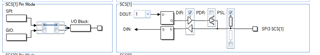
Halcogen Master


Code for Slave
int main(void)
{
/* USER CODE BEGIN (3) */
gioInit();
sciInit();
spiInit();
_enable_IRQ();
// SPI configuration: using SPI3 and chip select = 1
dataconfig1_t.CS_HOLD = TRUE;
dataconfig1_t.WDEL = TRUE;
dataconfig1_t.DFSEL = SPI_FMT_0;
dataconfig1_t.CSNR = SPI_CS_1;
gioSetBit(gioPORTB, 1, 0);
spiREG3->INT0 |= (1U << 8); // Enable SPI receive interrupt
spiEnableNotification(spiREG3, spiREG3->INT0); // Enable SPI RX interrupt notification
spiGetData(spiREG3, &dataconfig1_t, 1, Rx_SPI);
// Test loop with loopback mode
//spiEnableLoopback(spiREG3, Digital_Lbk);
while (1)
{
}
/* USER CODE END */
return 0;
}
/* USER CODE BEGIN (4) */
void spiEndNotification(spiBASE_t *spi)
{
spiGetData(spiREG3, &dataconfig1_t, 1, Rx_SPI);
gioSetBit(gioPORTB, 1, 1);
if(Rx_SPI[0] == 125){
gioSetBit(gioPORTB, 1, 1);
} else {
gioSetBit(gioPORTB, 1, 0);
}
}
/* USER CODE END */
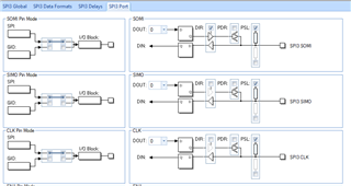
Halcogen Slave


Thx
Ariel

