This thread has been locked.

If you have a related question, please click the "Ask a related question" button in the top right corner. The newly created question will be automatically linked to this question.

MSPM0G3507: SPI DMA TX

Part Number: MSPM0G3507
Other Parts Discussed in Thread: SYSCONFIG

Tool/software:

Hello.

Trying to understand this..

What do I want to do ?

SPI peripheral TX DMA....the SPI will be running at 16 MHz minimum.

What I don't understand 

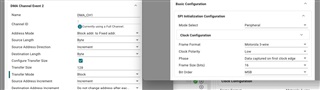
The triggering mechanism of the DMA configured in the SPI tab.

"Configure DMA Event 2 Trigger".   "SPI TX interrupt"

1. What has this go to do with interrupts ?

2. What is the DMA doing here...filling up the FIFO or just writing to the TX register...

3. The way I thought this would work (likely to be wrong) is that DMA would constantly fill the FIFO and be triggered when it gets to some level like, half full and therefor never miss a packet.

Any clues please...

Thanks.

Phil

  • 1) TRM (SLAU846B) Table 19-7 has 3x sets of "interrupt" control registers: CPU_INT, DMA_TRIG_RX, DMA_TRIG_TX. The first (as you guessed) controls routing of the interrupt conditions to the CPU. The other two route these conditions to the DMA, and each contains only a subset of the conditions [Ref TRM (e.g.) Table 19-44]. Calling them "interrupt" bits is a bit of verbal overloading, I suppose, but it's not completely unnatural.

    2) Writing to the TXDATA register stores the item into the FIFO.

    3) I'm not completely sure whether the DMA always fills the FIFO or only fills until the condition is satisfied (I suspect the latter). I think the deadlines end up being the same.

  • Thanks.

    I have sort of got this working now...

    The DMA starts and completes but for some reason it only transmits eight bytes, despite being setup for 128...

    I can't but think this is to do with the fact the TX FIFO is eight bytes...not sure what is going on.

  • Thanks..one thing, how do I reconcile SPI DMA setup with SPI frame size ?

    See attached.

  • 1) For Source/Destination Length you want Word (or whatever term Sysconfig uses for 16-bit).

    2) For Transfer Mode you want Single, so it moves one frame for each trigger. With Block, it transfers all (128) frames on a single trigger, overflowing the FIFO. (I suspect this is what you're observing.)

  • Thanks all working good now at 16 MHz.

    Unfortunately, it falls over at 32 MHz ! Thought it may do it...

  • Can you elaborate on "falls over"? [Hangs? Drops frames? Smears bits?]

    Datasheet (SLASEX6B) Sec 7.20.1 mentions that 32MHz requires (a) BUSCLK >= 64MHz (b) HSIO pins.

  • Hi Bruce....yes not a helpful comment..

    MCU is a slave.

    SPI is being driven differentially (LVDS) and signal integrity into master looks good on logic analyser including setup and hold into master.

    Link physical distance is small, five centimetres, but I care greatly about signal integrity.

    I have HSIO pins.

    I will have a look at the ck....can't find busclk anywhere ??

    Also wondering if the DMA is quick enough ?

    MCU is running at 32 MHz.

    At 32 Mbps - a sixteen bit word is dispatched  in 500 ns...I guess that is at least ten cycles so should be good enough...so think I have answered my own question.

    Thanks

  • Datasheet Sec 7.20.1 says that a slave is limited to 16MHz. [I'm pretty sure I also saw this in the TRM, but now I can't find it.]

    Both SPI units are in PD1, so BUSCLK=MCLK.

    I haven't found a statement on how long (MCLKs) a DMA transfer takes.

  • Thanks..missed that.

  • The G3519 datasheet (SLASFA2) Sec 7.18.1 indicates it doesn't have this restriction. [So I must not have read it in the TRM.]

    For that device either master or slave can run at 32MHz, assuming appropriate (2x) BUSCLK and HSIO.

    But I don't know when the G3519 will be (generally) available.