This thread has been locked.

If you have a related question, please click the "Ask a related question" button in the top right corner. The newly created question will be automatically linked to this question.

MSPM0G3507-Q1: Questions about TIMx event and DMA transfer mode

Part Number: MSPM0G3507-Q1
Other Parts Discussed in Thread: SYSCONFIG

Tool/software:

Hi MSP team,

I've got some questions regarding TIMx event for PWM and DMA transfer mode.

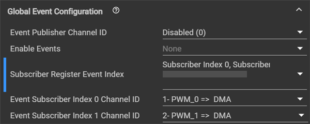
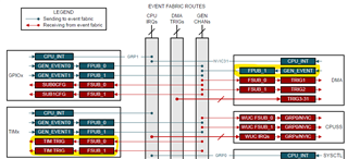
1) one FSUB_x register can be shared with 7ch of PWM?
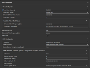
- Period: 1.25us

- PWM channel needed: 5-7ch

- Need to change duty per cycle

- There're two patterns of duty, and it comes out randomly (stored in DMA)

Used DMA -> GEN CHAN -> TIMx to set the duty value (not using CPU interrupt)

- There're two FSUB channels for subscribing value from DMA, but it needs to control up to 7 channels.

-> It has been implemented for using one channel (FSUB_0), but customer needs to confirm whether other PWM channels also can use the same FSUB_0.

Actually, I couldn't fully understand what FSUB_x registers are, and how the event works with GEN CHANs. Could you please explain this and confirm the questions from customer?
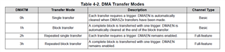
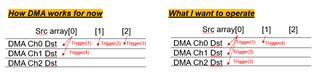
2) DMA trigger mode

- they made buffer with data for changing duty

- When DMA triggered, they would like to send the buffer data, and make it stop when the last data from buffer is finally sent.

In this case, which mode is most fit? and could you explain what is happening and the difference in each the single transfer and repeated single transfer mode?

I think the single transfer works for this case, could you confirm it please?

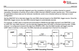
I also wonder what each DAMSA, DMADA, and DMASZ mean, and how it works.

Thank you for your help in advance.

Many thanks,

Yesol 

  • Hi Yesol,

    1) In the EVENT module of MSPM0, one event publisher could be subscribed by a lot of peripheral's event subscriber. 

    2) The single transfer of DMA means each transfer require a DMA trigger and DMA will be disabled after the DMA size of transfer is finished.

         The repeat single transfer means after DMA size has been transferred, DMA will keep enabled, and start to transfer from the initial state again.

    About the DMA items:

    • DMASA: DMA source address
    • DMADA: DMA destination address
    • DMASZ: DMA transfer size.
  • Thanks for your information, Pengfei.

    I have some more questions.

    Then, what if the TIMx publish the event for getting the duty value every cycle for 7ch PWMs, and the cc value is subscribed from DMA, 

    could whole 7ch PWMs can subscribe the DMA buffer?

       - As I configure the event that PWM0~6 as publisher and DMA as subscriber in CCS, the DMA (subscriber) could only be allocated for one PWM channel (publisher).

       - I am quite confused about which one should be the publisher and which one should be the subscriber, and wondered it actually be implemented for control 7ch PWMs by one DMA with generic event.

    And also, I'm curious about the DMA channels. If the compare value for each 7ch PWMs are different, could I designate each value using DMA channels in specific address?

    Thanks for your help in advance.

    Yesol

  • Hi Yesol,

    Let me clarify that the EVENT in MSPM0 is used to transfer from an trigger event to an pre-defined action.

    For example, if you use DMA as event publisher, the trigger event could be DMA transfer finished. And if the Timer is event subscriber, its re-defined action could be ZERO (load zero to the counter), LOAD (load LOAD value to the counter), or CC (load counter value to CC register). But I assume this is not you want.

    I think you could set a timer event as publisher (for example, PWM counter ZERO event), and set DMA as subscriber, so DMA transfer will be triggered each PWM period. The DMA source address is the buffer you set, and the destination address could be CC register of each PWM channel (Not test for this case, but CC register address could be found in TRM). You should set source and destination address for each DMA channel and each DMA channel is for a PWM channel.

  • Hi Pengfei,

    Thank you for the explanation.

    Now I wonder that if FSUB_x can be shared with 7ch PWMs' publisher.

    As I described, we should trigger the event for 7ch PWMs, but DMA seems only have two subscribers (FSUB_0, FSUB_1) to trigger for 7 channels of DMA.

    and when I'm configuring in CCS, I can only set for two index channel ID, even for global event configuration not for per channels.

    I think it seems impossible to make the event for 7ch PWMs with DMA channels.

    Please feel free to correct me If I've misunderstood anything.

    Many thanks

  • To elaborate a bit further on the question above, the 7ch PWMs implement with same clock frequency and want to trigger the DMA at the same time.

  • Hi Yesol,

    As the 7 PWM has the same frequency and trigger DMA at the same time, only one event publisher is needed for DMA trigger.

    But it is not possible to let 7 DMA channel transfer data at exactly same time (for example, they could not occupy BUS at same time), one way for achieve this is to use DMA cascading function. The next DMA channel transmission could be triggered after the last DMA channel finished. More details could be found in TRM.  

  • Hi Pengfei,

    Thanks for your explanation. I got the only one event needed. 

    But one thing confused is that when we config the 'trigger select' in Sysconfig, I could select FSUB_0 for each 7 DMA channels without error as external DMA channel trigger type.

    As you explained, I understood that for transfer to 7 DMA channel, should config the internal trigger for cascading function to trigger after the last DMA channel finished due to the DMA channel is not possible to let 7 channel transfer data at the same time.

    Does it matter if I config the all trigger select as FSUB_0 for 7 DMA channels?

    And if I should config it as internal trigger for channel1~6(like ch0 triggers ch1, ch1 triggers ch2...), then does it cause the delay to change the duty every cycle when the timer frequency is 1.25us?

    Many thanks for your help.

  • Hi Yesol,

    • 7 DMA channel are triggered by a same event publisher is also a way to achieve your function. 
    • And the delay is exist as these DMA channel could not operate at a same time, but the specific time may depends. Assume a 32MHz clock is used, a 16bit data is transferred for each channel, the estimation time delay may be around 4us. 
  • Hi Pengfei, 

    I configured the timer clock below, I will use 80MHz clock source to make 800kHz as PWM Freq with 100 period count.

    So, it takes 1.6us delay with 80MHz based on your explanation.

    But I wonder it really takes that much time for DMA? that means it needs 128cycles to transfer for one data.

    Could you please double check it takes 1.6us to transfer 16bit data per channel of DMA when we use 80MHz clock source?

    Thanks for your help in advance.

  • Hi Yesol,

    I estimate the DMA transfer time based on the assumption of DMA transfer 1bit for 1 cycle.

    But actually for a 32bit data bus, it should could transfer 32bit data a time within several cycles. 

    So the actual time may be less than 1.6us in 80MHz, you could test with below steps:

    1. Using DMA cascading channel function.

    2. Toggle a GPIO when the first DMA trigger is generated.

    3. Toggle the GPIO again when the last DMA channel is finished.

    4. Observe the GPIO pulse time to derive delay.

  • Hi Pengfei,

    I'm trying but I'm not sure what the DMA cascading channel function means. 

    Is this an automatically functioned in CCS when I configure the whole channels' trigger select as same FSUB0? 

    Also, I am stuck at DMA trigger with multi channels. So, I would like to do single transfer each data of the source for multi channels simultaneously using block address to fixed address. I attached picture what I want to achieve below.

    for now, I can see the DMA can transfer the next channel after the first source data has been transferred.

    But for control the 7PWM, All channel Scrarray[0] should be transferred at once trigger, and then increase the array num of SrcData, and transfer again the Scr array[1] for next trigger.

    Scr array should be independent datas, and this picture just for help to understand how data should be transferred with multi DMA channels.

    Could you please help me for debugging?

  • Hi Yesol,

    Sorry for late reply.

    #1 As for DMA cascading channel, it means one DMA channel (such as ch1)  could be triggered by another DMA channel transfer done event (such as ch0 done), please refer the below diagram.

    As for the configuration, the cascading channel could be achieved by setting CH0 trigger type as external DMA channel (FSUB_0), and setting CH1 trigger type as internal DMA channel and select DMA channel 0 as trigger source. And the same configuration could be done for ch2~ch15. 

    #2 I tested with DMA multi channel trigger, and the result shows the DMA channel1 will be triggered only when DMA channel 0 is transferred done (transfer size decrease to zero). That means we could only use multi channel trigger in "fix addr to fix addr" mode, otherwise, channel 1 will wait for all channel 0 data to be transferred and then start its transfer. And we need to change the source address manually. 

    Best Regards,

    Pengfei