This thread has been locked.

If you have a related question, please click the "Ask a related question" button in the top right corner. The newly created question will be automatically linked to this question.

LP-AM243: EDS ANALOG INPUT FOR ETHERNET/IP HOW TO WRITE 8 ANALOG INPUT TO ESD FILE ETHERNET/IP- CODESYS

Part Number: LP-AM243
Other Parts Discussed in Thread: ADS1115,

Tool/software:

I review your  EDS files. Only examples for Digital input and Digital Output. 

.  

I am working  a projects , using 8 Analog input , using examples program


Please help to write samples EDS file for these analog input.  (Also if you have some link examples please send )

Thanks,

Thien Tran

  • Hi Thien,

    if I understand correctly, you want to develop a project using Ethernet/IP and use Analog inputs and you are referring to Discrete I/O Profile example as starting point.
    First question is, do you want to implement a device profile? If not, then your device Profile should be Generic device.
    How do you want to model your Analog input points? There are two options for you, either you implement the Analog Input Point object, as specified in ODVA specification, Volume 1, section 5A-11, or you implement your own model.
    After you are clear about that, then you can easily adapt your EDS file, please use EZ-EDS tool from ODVA to create/adapt your EDS file.


    Best regards,
    Pourya

  • Hi Pourya.

    I can use Generic device. TI should have an example ESD file for IC2 OR SPI 8 channel each. Analog input & analog output. 

    We are manufacture, we need a faster solution ,

    EZ-EDS only help to modify the EDS file only.

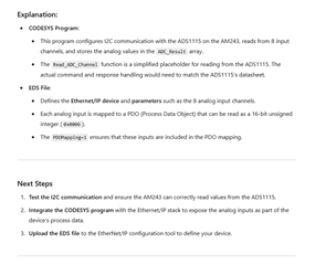
    I tried use chatgpt

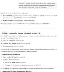
    Let’s write a complete program for the AM243 using CODESYS, which includes all the functions required to read 8 channels of analog data from the ADS1115. Also write eds file for ethernet/ip. 

    Please help to check the code composer program & eds file bellow. Thanks.

    // ADS1115 reading program in CODESYS

    // Declare variables
    VAR
    I2C_Master : I2C_Master; // I2C Master Communication
    ADC_Result : ARRAY[0..7] OF INT; // Store results from 8 channels
    ADS1115_Address : BYTE := 16#48; // I2C address of ADS1115
    Channel : INT; // To loop through the channels
    Raw_Value : INT; // To store raw ADC value
    END_VAR

    // Initialize the I2C master communication
    I2C_Master.Device := ADS1115_Address;
    I2C_Master.Mode := I2C_Mode_Transfer;
    I2C_Master.ClockSpeed := 100000; // 100 kHz

    // Function block to read 8 channels
    FOR Channel := 0 TO 7 DO
    // Assuming you are configuring the ADS1115 to read on each channel:
    Raw_Value := Read_ADC_Channel(Channel); // This function should be implemented to read from the ADS1115
    ADC_Result[Channel] := Raw_Value;
    END_FOR

    // Function to read from ADS1115 channel (simplified version)
    FUNCTION Read_ADC_Channel : INT
    VAR_INPUT
    Channel : INT; // Channel to read (0-7)
    END_VAR
    VAR
    ADC_Command : ARRAY[0..1] OF BYTE; // Command to send to ADS1115
    Result : INT; // Store the result of the conversion
    END_VAR

    // Set the command to select the channel and start conversion
    ADC_Command[0] := 16#40 + Channel; // Example command for channel selection
    ADC_Command[1] := 16#00; // Example config byte

    // Write the command to ADS1115 to start conversion
    I2C_Master.Write(ADC_Command, 2);

    // Wait for the conversion to complete (simple delay for simulation)
    DELAY(500); // Add your actual conversion time here based on ADS1115 specs

    // Read the result from ADS1115
    I2C_Master.Read(ADC_Command, 2);

    // Return the result (combine bytes)
    Result := (ADC_Command[0] SHL 8) OR ADC_Command[1];

    RETURN Result;
    END_FUNCTION

    *********************************

    [Device]
    DeviceType=Ethernet/IP
    DeviceName=AnalogInputDevice
    VendorName=YourCompany
    ProductName=ADS1115 Analog Input
    ProductCode=0x1234
    Revision=1.0

    [IdentityObject]
    ObjectType=Identity
    VendorID=0x0000
    DeviceType=0x0001
    ProductCode=0x1234
    Revision=1.0
    ProductName=ADS1115 Analog Input

    [ConnectionManager]
    SupportedConnectionTypes=0x01 ; Explicit messaging (commonly used)

    [Parameters]
    Parameter_1=Analog Input 1
    Parameter_2=Analog Input 2
    Parameter_3=Analog Input 3
    Parameter_4=Analog Input 4
    Parameter_5=Analog Input 5
    Parameter_6=Analog Input 6
    Parameter_7=Analog Input 7
    Parameter_8=Analog Input 8

    [Connection]
    ConnectionType=0x01
    ConnectionName=AnalogInputConnection
    Protocol=Ethernet/IP
    ServiceType=0x04 ; I/O Connection
    ConnectionID=0x01

    [Inputs]
    Input_1=Analog Input 1
    Input_2=Analog Input 2
    Input_3=Analog Input 3
    Input_4=Analog Input 4
    Input_5=Analog Input 5
    Input_6=Analog Input 6
    Input_7=Analog Input 7
    Input_8=Analog Input 8

    [Outputs]
    Output_1=Analog Output 1

    [ObjectDictionary]
    [1000]
    ParameterName=Analog Input 1
    DataType=0x0006 ; UINT16
    AccessType=ro
    PDOMapping=1

    [1001]
    ParameterName=Analog Input 2
    DataType=0x0006 ; UINT16
    AccessType=ro
    PDOMapping=1

    [1002]
    ParameterName=Analog Input 3
    DataType=0x0006 ; UINT16
    AccessType=ro
    PDOMapping=1

    [1003]
    ParameterName=Analog Input 4
    DataType=0x0006 ; UINT16
    AccessType=ro
    PDOMapping=1

    [1004]
    ParameterName=Analog Input 5
    DataType=0x0006 ; UINT16
    AccessType=ro
    PDOMapping=1

    [1005]
    ParameterName=Analog Input 6
    DataType=0x0006 ; UINT16
    AccessType=ro
    PDOMapping=1

    [1006]
    ParameterName=Analog Input 7
    DataType=0x0006 ; UINT16
    AccessType=ro
    PDOMapping=1

    [1007]
    ParameterName=Analog Input 8
    DataType=0x0006 ; UINT16
    AccessType=ro
    PDOMapping=1

    ********************************************

  • Hi Thien,

    the generated code for CODESYS is for your soft PLC side, but I guess that is not what you meant to ask from Chatgpt. 
    You have your AM243x board which uses ADC to read the values and pass them to Analog Input Object in EtherNet/IP side, and your PLC, using the EDS file can read and interpret the values, is that what are you trying to do? 
    If yes, then the whole generated CODESYS code is useless for you. 

    I didn't understand, what you mean by "EZ-EDS only help to modify the EDS file only.". What else did you expect from EZ-EDS? Basically you have to add the parameters in Param section, as I see chatgpt has done for you, then you need to adapt your assemblies and if necessary, under Connection Manager, the Exclusive Owner connection.
    What the "adaptation" or "changes" should be, depends on your application, In other words, you need to have clear understanding about assemblies and your Exclusive Owner connection. 

    Best regards,
    Pourya

  • Hi Pourya.

    I worked with AM64 - LP-AM243 from your examples ethernet/ip. Codesys , I can turn on Led on and off. (I2C )

    You have your AM243x board which uses ADC to read the values and pass them to Analog Input Object in EtherNet/IP side, and your PLC, using the EDS file can read and interpret the values, is that what are you trying to do?  Yes.

    I trained CHATGPT (Codesys- Ethernet /IP , this will generate the ESD file , but I am not sure if it is correct ) After I will use EZ-EDS to change few parameter.

    1) I need examples programs can read 8 Analog input  I am not familar with TI solfware, but if you have a good working example , So I can modify.

    2) I need a example programs from TEXAS instruments  read the values and pass them to 8 Analog Input Object in EtherNet/IP side.

    3) I need a working ESD file.

    If posible please help.

    If you have some consultant , I need to have these program to finish ASAP 

    my email: vnsemi@gmail.com

                     ttran@nktechnologies.com

    Thanks,

  • Hi Thien,

    please clarify the following points to avoid confusion:
    1) Did you mean, you have tried to run an example with AM64x running CODESYS? What does it have to do with your final Project? Which brings me to next question:
    2) What is your target Hardware? is it AM243x or AM64x?

    Regarding your questions:
    1) I need examples programs can read 8 Analog input  I am not familar with TI solfware, but if you have a good working example , So I can modify.

    I'm not aware of any example in MCU+SDK that can read Analog values from an external ADC chip ( ADS1115 ). There is however an example which you can use to port it for AM243x. See ADS1115-C-EXAMPLE-CODE Support software | TI.com 

    2) I need a example programs from TEXAS instruments  read the values and pass them to 8 Analog Input Object in EtherNet/IP side.

    There exist no such example. You need to to implement the Analog input object yourself (as asked before, how do you want to model your Analog Input in Ethernet/IP, either you should implement Analog Input Object as specified in ODVA specification, or you have to implement your own model).
    Please refer to Discrete I/O example or Generic Device example as a starting point to develop your project.
    Here is the APIs for EtherNet/IP stack: EtherNet/IPTm Adapter: API Reference


    3) I need a working ESD file.

    I would say, the more time consuming task would be #2 (developing your project in C). After that, let me know if you need help with your EDS file by sending your EDS file and I can review it. 

    Best regards,
    Pourya