This thread has been locked.

If you have a related question, please click the "Ask a related question" button in the top right corner. The newly created question will be automatically linked to this question.

MSPM0G3507: Application programmed via I2C BSL fails to execute properly

Part Number: MSPM0G3507
Other Parts Discussed in Thread: UNIFLASH

Tool/software:

I'm working on a carrier board with a TI AM62-based SoM and a MSPM0G3507 MCU.  Using the example project bsl_host_mcu_to_mspm0g1x0x_g3x0x_target_i2c (SDK 2.04.00.06) as a guide, I developed a "BSL host"  program to run on the SoM that updates the application firmware on the MCU via I2C BSL.  Accordingly, two GPIO lines from the SoM are connected to NRST and PA18 (default BSL_INVOKE) on the MCU respectively, and an I2C bus on the SoM is connected to the MCU's I2C0.  The desired MCU firmware image was built in Code Composer Studio v20.1.1 using the TI Clang v4.0.2.LTS toolchain; the Arm hex utility was configured to generate an object file in TI-TXT format, and I used the MSPM0_BSL_GUI utility to convert the latter to a header file for inclusion in the host program.

The host program does the following:

  • Invokes BSL via GPIO
  • Opens the I2C interface and sends the 'Connection' command
  • Sends the 'Unlock Bootloader' command with default password to allow execution of protected commands
  • Sends the 'Mass Erase' command to erase the MCU's MAIN flash memory
  • Writes the new application to the MCU using multiple 'Program Data' commands
  • Sends the 'Start Application' command

When executed, the program runs to completion without errors.  However, the MCU does not appear to be executing the updated image: its power consumption is lower than expected, and it does not respond to unrelated (non-BSL) commands sent from the SoM over a separate UART channel.

I'm confident that the program is sending commands and handling responses properly.  While debugging, I received "BSL locked" errors upon sending a protected command if it had been too long since 'Unlock Bootloader' had been sent, and "invalid address or length alignment" errors when attempting to write the firmware application before realizing that the target address and data length had to be 8-byte aligned.

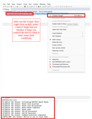
Subsequently, when I connected an XDS110 debug probe to the MCU and attempted to load the firmware application using the CCS debugger, I received the following error:

Error connecting to the target:  Connection to MSPM0 core failed.  Possible root causes: 1) Debug access within NONMAIN was disabled or enabled with password. 2) Peripheral mis-configuration (e.g improper watchdog or clock).  To see a more detailed diagnostic of the issue, please press the 'Read boot diagnostic' button.

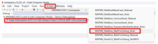
After investigating what to do, I launched the MSPM0_Factory_Reset_Tool and executed a Mass Erase operation; I was then able to successfully load and execute the firmware application.  Note that the file loaded by the debugger had been used to generate the corresponding .txt file which in turn was converted to the header file included in the host program.

Any thoughts about what might be wrong?  Thanks.

  • Hi Dave,

    The process looks good for me. To figure out what happens, can you only process the flow below:

    • Invokes BSL via GPIO
    • Opens the I2C interface and sends the 'Connection' command
    • Sends the 'Unlock Bootloader' command with default password to allow execution of protected commands
    • Sends the 'Mass Erase' command to erase the MCU's MAIN flash memory
    • Writes the new application to the MCU using multiple 'Program Data' commands

    Then, you can use the UNIFLASH to read out the flash memory, and compare it to original one to see any differences:

    Check the MAIN flash area (0x0000.0000)and NONMAIN flash area (0x41C0.0000.

  • Hi Sal,

    Thanks for your rapid response.  I used the XDS110 probe to load a valid application into the flash memory, and launched UniFlash to display the contents of the memory.  Both the application (starting at address 0x00000000) and the NONMAIN registers (starting at 0x41C00000) looked valid.  I then executed the update sequence above and attempted to refresh the display of the flash contents starting at location 0x00000000, but received the following error:

    [ERROR] CORTEX_M0P: Error connecting to the target: (Error -614 @ 0x0) The target indicates there is an error condition from a previous SWD request. Clear the error the condition, and try the SWD request again. (Emulation package 20.0.0.3298)

    I power-cycled the target device and tried again, but received the same error.  I also power-cycled the XDS110, but no joy.  Thinking that a mass erase was likely necessary, I used UniFlash to execute a "Mass erase auto" operation.  Upon successful completion, I power-cycled the target and relaunched UniFlash.  Flash memory starting at 0x00000000 was all F's, while the NONMAIN registers looked fine.

    Any ideas?

    Dave L.

  • Hi Dave,

    I suppose you are using the BOM BSL for I2C interface.

    I then executed the update sequence above and attempted to refresh the display of the flash contents starting at location 0x00000000, but received the following error:

    When it comes to this error, then you can follow below method to check its application code without executing mass erase:

    1. Connect PA18 to VCC

    2. Then press force the NRST to Low more than 1s, or repower the MCU (keep connecting PA18 to VCC)

    3. Use Uniflash to read out the firmware, it is expected to connect now.

    What I suspect is that the application code is not fululy integrated which cause the issue.

    B.R.

    Sal

  • Hi Sal,

    After asserting BSL_INVOKE and resetting the MCU, I got the following error when attempting to refresh the flash memory read-out:

    [ERROR] CORTEX_M0P: Error connecting to the target: (Error -6305) PRSC module failed to write to a router register. (Emulation package 20.0.0.3298)

    Thanks,

    Dave L.

  • Hi Dave,

    That looks abnormal. If the Mass erase could success, the BSL invoke should also work. Is the NRST externally connected?

    Could you share the txt file here for my reference?

    B.R.

    Sal

  • Hi Sal,

    Both the BSL_INVOKE and NRST signals are connected to GPIO lines on the SoM, so I had been manipulating their levels using the Linux 'gpioset' command from the SoM.  I had been asserting BSL_INVOKE (i.e., set high) for 30 seconds in one shell, asserting NRST (i.e., set low) for 2 seconds in another shell, and then refreshing the memory read-out in UniFlash.

    Recalling that there is a pushbutton on the PCB that can also drive NRST low, I tried asserting BSL_INVOKE for 30 seconds via gpioset, depressing the NRST pushbutton for 2 seconds, and then refreshing UniFlash.  This time, the read-out was successful.  A brief visual inspection showed that the start of the image looked correct, but the end appeared to be corrupted.

    For a direct comparison, I exported the memory contents from 0x0000 to 0x7240 (encompassing the entire image) of a properly programmed MCU, and then exported that of a MCU after an update attempt.  It appears that from offset 0x0000 to 0x1FFF, the memory contents are identical; from 0x2000 onward, they are completely different.  (The image ends at offset 0x722F.)

    I've attached the .txt file; I tried to attach the two binary files but it seems that the forum uploader doesn't allow it.

    Thanks,abx_auto_pmic.txt

    Dave L.

  • Hi Dave,

    For a direct comparison, I exported the memory contents from 0x0000 to 0x7240 (encompassing the entire image) of a properly programmed MCU, and then exported that of a MCU after an update attempt.  It appears that from offset 0x0000 to 0x1FFF, the memory contents are identical; from 0x2000 onward, they are completely different.  (The image ends at offset 0x722F.)

    So this looks like the host command to load firmware is broken. Then the image in M0G is incorrect.

    When the MCU run to the incorrect the flash address, then it will enter some fault conditions, which makes the M0G lose connections.

    By the way, there has additional scripts in CCS which might be helpful to connect the device when the MCU run into fualt conditions:

    I suggest you check how your host send the firmware out, use a logic analyzer to check what the data you sent to M0G.

    Update: I can try your txt in two LP and connect with I2C interface to see any issues.

    B.R.

    Sal

  • Hi Sal,

    Your suspicion was spot-on.  After reexamining my adaptation of Host_BSL_write_memory() from the bsl_host_mcu_to_mspm0g1x0x_g3x0x_target_i2c project, I realized that while I was properly incrementing the target address and decrementing the remaining byte count after each loop iteration, I hadn't been incrementing the data pointer.  Adding this fixed the issue: I can now successfully update the MCU application.

    Thank you very much for your assistance.  I'm embarrassed that I didn't catch this earlier.

    Dave L.