Part Number: TMS570LS3137
Tool/software:
Hello everyone,
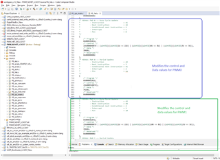
I'm currently working with the N2HET peripheral on the TMS570LS3137 microcontroller. After reviewing the technical reference manual to understand the capabilities of the N2HET module, I explored the HALCoGen-generated code to see how PWM and other timing functions are implemented. However, I encountered a section that I'm having trouble understanding.
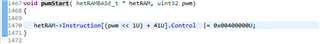
Specifically, in the pwmStart function, the following code is used:
void pwmStart(hetRAMBASE_t * hetRAM, uint32 pwm)
{
hetRAM->Instruction[(pwm << 1U) + 41U].Control |= 0x00400000U;
}
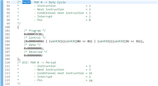
I'm trying to understand the logic behind the expression [(pwm << 1U) + 41U]. I assume that the pwm parameter refers to a specific PWM channel, but I couldn’t find clear documentation explaining why the index calculation is done this way, or how it maps to the actual instructions used to control PWM behavior in the N2HET RAM.
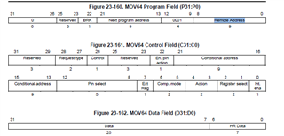
Additionally, I’d like to know more about how to determine which HET instruction index to use for operations like starting/stopping PWM or reading edge counters. The reference manual provides instruction details but doesn’t seem to explain how those are organized or accessed.
Could someone explain:
-
How the instruction indexing (e.g.,
(pwm << 1U) + 41U) is determined? -
Where this mapping between PWM channels and instruction RAM locations is defined?
-
How to properly interface with the N2HET instruction set to perform actions like starting/stopping PWM or reading counters?
Any clarification or pointers to documentation/examples would be greatly appreciated.
Thanks in advance!